


–
6
–
EN
Setup
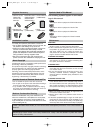
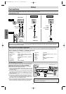
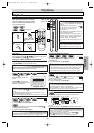
Connection to a TV
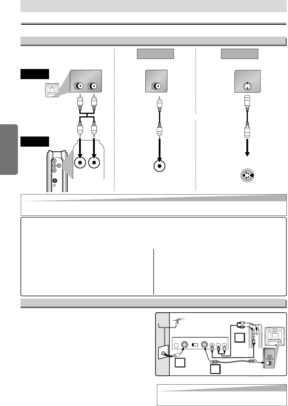
Connections
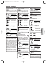
If your TV has AUDIO/VIDEO input jacks, see the following instructions.
Setup
S-VIDEO
OUT
VIDEO
OUT
AUDIO OUT
DIGITAL
AUDIO OUT
COAXIAL
L
R
AUDIO OUT
L
R
TO
SPEAKER
LR
AUDIO IN
VIDEO IN
VIDEO
OUT
S-VIDEO IN
S-VIDEO
OUT
(Analog)
AUDIO OUT
VIDEO OUT
TV
Method 1
Good pictureBasic Audio
Method 2
Better picture
S-VIDEO OUT
Video
cable
(supplied)
Audio cable
(supplied)
S-Video
cable
(commercially
available)
This unit
Hint
Hint
•Connect this unit directly to the TV. If the Audio/Video cables are connected to a VCR, pictures may be distorted
due to the copy protection system.
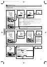
After you have completed connections
•
Hit the input selector button (usually TV/VIDEO, INPUT or AUX) on your TV to switch an appropriate external input channel (usually
near channel 0) for viewing the picture from this unit. If the picture does not appear, also refer to the manual accompanying your TV.
INPUT MODES FOR COMMON TV BRANDS (Example)
• Listed below are inputs for common brand name TV’s.
Admiral: AUX
Curtis Mathis: LINE1, LINE2, 00, 90, 91, 92, 93
GE: INPUT, TV/VCR, 00, 90, 91, 92, 93
Hitachi: INPUT, AUX
JVC: A/V CHANNEL, INPUT1, SVIDEO,
INPUT2
Kenwood: AUX
LXI-Series: 00
Magnavox: AUX CHANNEL
Panasonic: TV/VIDEO
RCA: INPUT, TV/VCR, 00, 90, 91, 92, 93
Samsung: TV/VIDEO
Sanyo: VIDEO
Sharp: 00
Sony: VIDEO1, VIDEO2, VIDEO3
Toshiba: TV/GAME
Zenith: 00
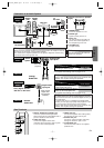
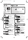
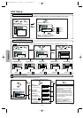
RF Modulator Connection
If your TV has Antenna in jack only, it is still possible to
connect this unit to your TV by using a STEREO
AUDIO/VIDEO RF Modulator (commercially available).
In this case, follow the instructions below.
1) Connect the AUDIO/VIDEO output jacks of this unit to the
AUDIO/VIDEO input jacks of your RF Modulator by audio
and video cables.
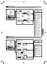
2) The antenna input jack of your TV may have been already
occupied. If so, disconnect the RF cable from your TV, and
then connect the RF cable to your RF Modulator (usually
marked “ANT IN”).
3)
Connect your RF modulator to your TV by another RF cable.
4) Set your RF modulator’s channel 3/4 switch to either 3 or
4, whichever the TV channel is least used in your area. If
your RF modulator has a Modulator/Antenna switch, set it
according to your RF modulator’s manual.
5) Turn on your TV and choose the same channel as you set
the RF modulator’s channel 3/4 switch to.For more details,
follow the instructions supplied with the RF Modulator.
Hint
Hint
• The quality of picture may become poor if the unit is con-
nected to an RF Modulator.
S-VIDEO
OUT
VIDEO
OUT
AUDIO OUT
DIGITAL
AUDIO OUT
COAXIAL
L
R
Stereo Audio/Video RF Modulator
(commercially available)
TO TVCHANNEL VIDEO AUDIO
RL34
ANT IN
AC 120V
(Back of TV)
Audio/Video
Cables
(Supplied)
(Back of this unit)
RF Cable (Not supplied)
Antenna
Cable
Signal
3
2
1
Antenna in jack
or
(INPUT)
(OUTPUT)
E61S5UD_ENSP.qx33 05.4.21 1:23 PM Page 6