


31
EN
OPTIONAL SETTINGS / MISCELLANEOUS
M
ISCELLANEOUS
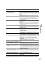
AT TACHING A WALL MOUNT BRACKET (SOLD SEPARATELY)
The following is a description of the method for attaching a wall mount to this TV.
When performing this operation, refer to the instruction manual included with the wall mount kit.
You need the following wall mount unit (commercially available) for this TV.
EZLCDM-02: Market Link USA, Inc. (www.easymount.com)
#
CAUTION
•Any damage caused by incorrectly attempting to mount this TV is not covered under the terms of the
manufacturers warranty.
• This LCD Color TV may be used only with EZLCDM-02 manufactured by Market Link USA, Inc. Wall
Mount. Use with other wall mounts may result in instability causing possible injury.
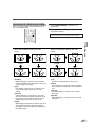
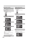
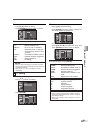
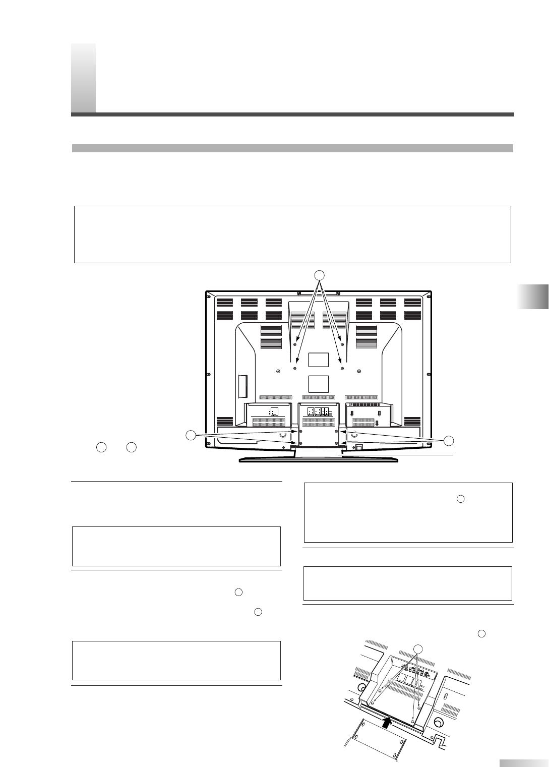
1 Tu rn this TV over and place it screen-first onto a
table which has a soft cloth draped over it.
Place this TV in a way so that the stand hangs
over the edge of the table.
2 Remove the stands from this TV.
Unscrew the M4 screws indicated by and
remove the stand.
Also, unscrew the M4 screws indicated by
.
Please be careful with the TV after you
remove the stand.
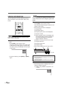
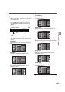
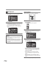
3 Attach the left and right TV rails to this TV using
the four Phillips screws M4 x 12mm bolt and four
M4/M5 washers included with the wall mount kit.
You don’t need to use the lock washers for
mounting this TV.
4 Attach this TV to the wall.
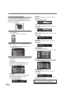
* If you want to attach the stand of this TV again,
insert the stand slowly as illustrated below and
drive M4 screws in the 4 threaded holes ( ).
1
NOTE:
• Refer to the instruction manual included with the
wall mount when securing this TV to the wall.
NOTE:
• The M4 screws and stand you have removed are
necessary for reattachment at a later date. Make
sure to keep them in a safe place.
2
1
NOTES:
• Make sure to use a table which can support the
weight of this TV and is larger than this TV.
• Make sure the table is in a stable location.
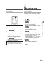
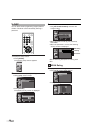
ANT. IN
AUDIO OUT
L
R
AUDIO
HDMI IN
L
R
DIGITAL
AUDIO OUT
(COAXIAL)
HDMI
S-VIDEO1
S-VIDEO2
COMPONENT2
AUDIO
L
RPr
Pb
Y
VIDEO2
VIDEO
AUDIO
L
R
VIDEO1
VIDEO
AUDIO
L
R
COMPONENT1
AUDIO
L
RPr
Pb
Y
2
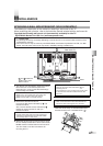
Rear of this TV
2
1
1
1
Stand
* and indicate the
position of the screw
holes on this TV.
NOTES:
• Only use the screw holes indicated by for
mounting this TV.
•For instructions on how to attach the TV rails, refer
to the instruction manual included with the wall
mount kit.
2
1