RS232-RS485 Convertor Manual V1.02 28/06/01
3
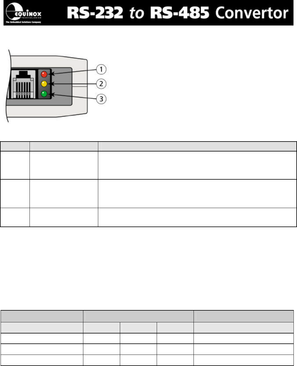
2.1 RS-232 to RS-485 Status LED Indicators
Figure 4
No LED Colour Status Description
1 Red Indicates that the PC has enabled RS-485 transmission.
This means that the RS-485 driver has been enabled allowing
the convertor to drive the RS-485 line to the remote system.
2 Yellow Indicates that the remote RS-485 system is transmitting data
to the PC through the convertor. The LED will flash when
data is being transmitted.
3 Green PC is transmitting data to the remote RS-485 system.
The LED will flash when data is being transmitted.
Figure 5
2.2 Input Power Supply Requirements
The power supply requirements for the ‘RS-232 to RS-485 Convertor Module’ are detailed
in the table below. The current drawn by the module from the external power supply varies
from a Standby Current when no data transfer is taking place to an Active Current when data
transfer is taking place.
Parameter Values Units
Min Typical Max
Standby Current 10 mA
Active Current 1000 mA
Supply Voltage 8.3 9.0 9.9 V DC
Figure 6


