


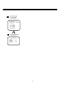
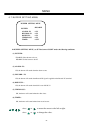

MENU
Note:
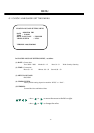
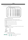
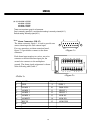
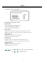
Alarm Connectors (DB-15)
PIN # NAME PIN # NAME
1 GND 9 GPIN 2
2 ALMIN 1 10 DISK-FULL
3 ALMIN 2 11 GPOUT 1
4 ALMIN 3 12 GPOUT 2
5 ALMIN 4 13 ALM NC
6 ALMRST 14 ALM NO
7 REC IN 15 ALM COM
8 GND
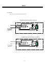
The alarm connector, figure 1, is used to provide one
sensor alarm input for each camera input.
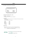
For easy operation, an alarm extension board,
figure 2, is provided to connect to the alarm
connector.
Each alarm input requires two wires, one wire
connects to the desired alarm input pin, the
second wire connects to the multiplexer
ground. The alarm signal assignment is shown
at the following table, table 1.
915
1
8
<Figure 1>
<Table 1>
<Figure 2>
P
S
R
4
D
0
0
6
0
A
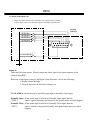
8 7 6 5 4 3 2 1
9 10 11 12 13 14 15
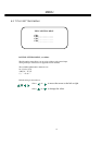
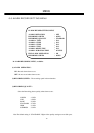
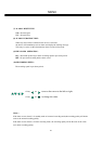
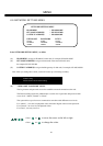
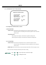
MENU
(4)~(5) ALARM -1 TYPE:
ALARM -2 TYPE:
ALARM -3 TYPE:
ALARM-4 TYPE:
20
There are two alarm types for all cameras.
One is normally open(N.O.) and the other setting is normally closed (N.C.).
Default setting: Normally open(N.O.)