


AVT 200HD Tuner • Setup Guide (Continued)
2
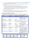
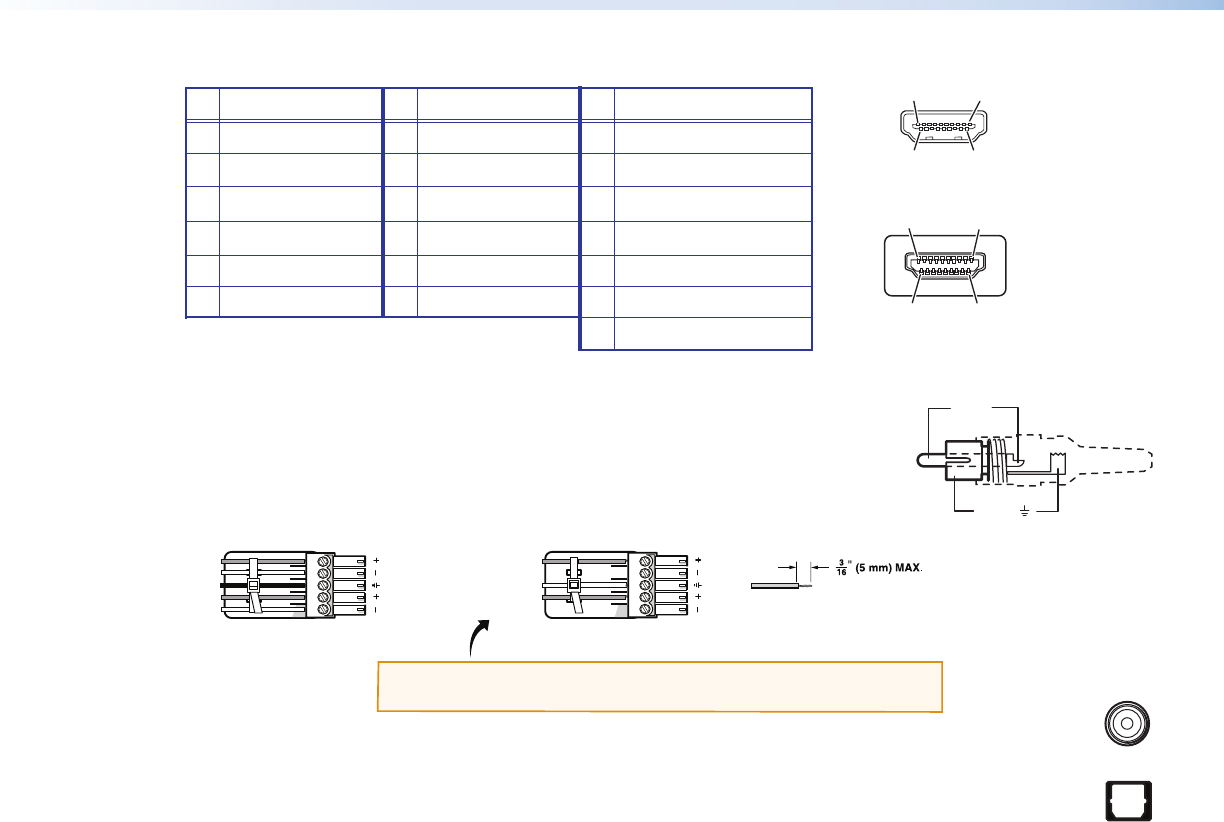
z HDMI — Connect an HDMI output device to this HDMI connector (
e
on the rear panel diagram on the previous
page) for digital video output. Supports 480p, 720p, and 1080i resolutions. See the table below for pin assignments.
Pin
Signal
Pin Signal
Pin
Signal
1 TMDS data 2+ 7 TMDS data 0+ 13 CEC
2 TMDS data 2 shield 8 TMDS data 0 shield 14 Reserved (NC on device)
3 TMDS data 2– 9 TMDS data 0– 15 SCL
4 TMDS data 1+ 10 TMDS clock+ 16 SDA
5 TMDS data 1 shield 11 TMDS clock shield 17 DDC/CEC ground
6 TMDS data 1– 12 TMDS clock– 18 +5 V power
19
Hot plug detect
HDMI
Type A Receptacle
1
18 2
19
HDMI
Type A Plug
1
182
19
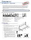
5. Connect the audio output. Connect a speaker set, amplifier, receiver, or other audio output device to one or more of
the following connectors:
z RCA — Connect an audio output device to these RCA connectors (
f
) for unbalanced
analog audio output as shown at right.
z Captive screw — Connect an audio output device to this 5-pole captive screw
connector (
g
on the rear panel diagram) for balanced or unbalanced analog audio as
shown below:
Balanced Audio Output
Unbalanced Audio Output
Tip
Ring
Tip
Ring
LR
Sleeve
Do not tin the wires!
Tip
NO Ground Here
Sleeve
NO Ground Here
Tip
LR
CAUTION: For unbalanced audio, connect the sleeves to ground.
DO NOT connect the sleeves to negative (–) contacts.
z Coax — Connect a digital audio output device to this coaxial RCA jack (
h
) for S/PDIF signal transmission.
z Optical — Connect a digital audio output device to this TOSLINK™ fiber optic connector (
i
) for S/PDIF
signal transmission.
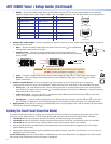
6. Connect control devices. Connect a computer or control system to one of these AVT ports to remotely
configure and control the tuner via the Windows
®
-based software, SIS™ commands, or the embedded web pages.
z RS232 port — For serial RS-232 control, connect a host computer or control system to the Tx, Rx, and _ (ground)
pins of this 5-pin captive screw connector (
k
). The default protocol for this port is 9600 baud, 1 stop bit, no parity,
8 data bits, and no flow control.
z LAN Ethernet port — Connect the AVT to an Ethernet LAN or WAN via this RJ-45 connector (
l
) to control the
tuner via computer using an Internet browser.
z Config port — Connect a USB cable (USB A to mini B) between the computer and this USB port (
b
on the front
panel diagram on page 3) to use the Windows-based control software or SIS commands, or to upload firmware.
7. Apply power to the AVT by connecting a standard IEC power cord (provided) from a 100 to 240 VAC, 50-60 Hz power
source to the AC power receptacle (
a
).
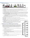
Locking the Front Panel (Executive Mode)
To prevent accidental changes to settings, you can lock the AVT front panel or IR controls by placing the tuner in lock
(executive) mode. While the AVT is in lock mode, RS-232, USB, Ethernet, and IR communication remain available.
• Lock mode 1 locks all front panel functions. IR, RS-232, and Ethernet control are available.
• Lock mode 2 locks all front panel functions except volume control. IR, RS-232, and Ethernet control are available.
• Lock mode 3 locks out all IR access. RS-232, Ethernet, and the front panel controls are available.
1. Press and hold the Menu and Next buttons simultaneously until Exec Mode Select appears in the LCD window
(approximately 3 seconds).
2. Rotate either Adjustment knob until the desired mode name (Disable, Complete, Volume Only, or IR Lockout) is
displayed in the LCD window.
To exit lock mode, press and hold the Menu and Next buttons until Exec Mode Select is displayed in the LCD window,
then rotate either Adjustment knob until DISABLE is displayed.
Tip (+)
Sleeve ( )
COAX
OPTICAL