


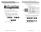

The CVC 200 Component Video Converter converts all SMPTE
standard component video formats to RGBS or RGBHV video. The
CVC 200 can also strip sync-on-green (SOG) from RGsB video.
The converter outputs converted RGBS or RGBHV video on BNC
connectors. Figure 1 shows a typical CVC 200 application.
O
U
T
P
U
T
I
N
P
U
T
F
O
R
M
A
T
Extron
CVC 200
Video Converter
HDTV
Set Top Box
Large Screen
Rear Projector
LCD Projector
Video Monitor
DVD
or
or
Figure 1 — Typical CVC 200 application
The component video input formats include DVD, Betacam
®
video, and
HDTV component video. The RGsB video input can be computer video
or NTSC/PAL video.
Mounting
The CVC 200 can be rack mounted using one side of a 1U Universal
Rack Shelf (part #60-190-01) or 1U Basic Rack Shelf (part #60-604-01).
UL requirements
The following Underwriters Laboratories (UL) requirements pertain to
the installation of the CVC into a rack.
1. Elevated operating ambient temperature — If the equipment
installed in a closed or multi-unit rack assembly, the operating
ambient temperature of the rack environment may be greater
than room ambient temperature. Therefore, install the CVC in an
environment compatible with the maximum ambient temperature
(Tma = +122 °F, +50 °C) specified by Extron.
2. Reduced air flow — Install the equipment in a rack so that the
amount of air flow required for safe operation of the equipment is
not compromised.
3. Mechanical loading — Mount the equipment in the rack so that
a hazardous condition is not achieved due to uneven mechanical
loading.
4. Circuit overloading — Connect the equipment to the supply
circuit and consider the effect that circuit overloading might
have on overcurrent protection and supply wiring. Appropriate
consideration of equipment nameplate ratings should be used
when addressing this concern.
5. Reliable earthing (grounding) — Maintain reliable grounding
of rack-mounted equipment. Pay particular attention to supply
connections other than direct connections to the branch circuit
(e.g. use of power strips).
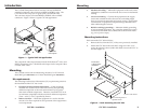
Mounting instructions
Rack mount the CVC 200 as follows:
1. Remove the feet from the CVC, if they were previously installed.
2. Mount the CVC 200 on the rack shelf, using two 4-40 x 3/16”
screws in opposite corners (under the shelf) to secure the CVC to
the shelf (figure 2).
(2) 4-40 x 3/16" Screws
Use 2 mounting holes on
opposite corners.
False front panel
uses 2 front holes.
#10-32 Screw
w/ Nylon Captive
Cap Washer
C
V
C
2
0
0
Figure 2 — Rack mounting the CVC 200
Mounting
Introduction
CVC 200 • Installation
1
CVC 200 • Installation
2