1
DSC 3G-HD A Scaler • Setup Guide
The Extron DSC 3G-HD A is a 3G-SDI to HDMI scaler that converts 3G-SDI, HD-SDI, and SD-SDI signals to HDMI. It accepts
and scales SMPTE video resolutions from 480i and 576i up to 1080p @ 60 Hz and 2K, and offers multiple output rates up to
1920x1200, including HDTV 1080p/60 and 2k. Stereo audio embedding and an SDI input loop-through are also provided.
This setup guide provides step-by-step instructions for an experienced user to set up and configure a DSC 3G-HD A. It covers
how to perform basic operations using the front panel controls and selected Simple Instruction Set (SIS
™
) commands.
NOTE: For full installation, configuration, menus, connector wiring, and operation details, see the DSC 3G-HD A and
DSC HD-3G A User Guide, available at www.extron.com.
Installation
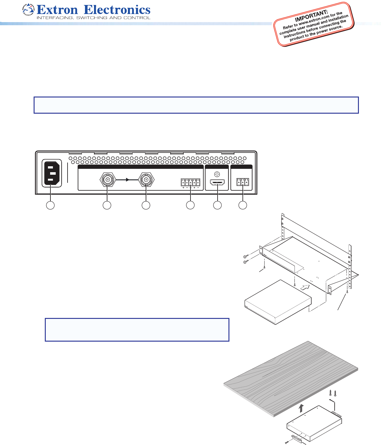
Rear Panel Features
HDMI
3G/HD/SD-SDI LOOP THRU
100-240V ~ 0.3A MAX
50-60 Hz
DSC 3G-HD A
REMOTEOUTPUT
AUDIO
INPUT
L
R
2
3
1
5
4
RS-232
Tx Rx G
6
Mounting and Cabling the DSC 3G-HD A
1. Disconnect power: Turn off or disconnect all equipment power sources.
2. Mount the unit: (Optional) Mount the DSC 3G-HD A either in a rack using
shelf mounting brackets (RSU 129 or RSB 129) or under furniture using
furniture mounting brackets (MBU 125) (see gures 1 and 2 at right). A false
face plate (RFF 052) can be tted on top of the low prole DSC if desired.
3. Connect the input: Connect an SDI video source to the 3G/HD/SD-SDI
BNC input connector
b
.
4. Connect a monitor: (Optional) Connect a local monitor to the buffered
Loop Thru SDI connector
c
.
5. Connect analog audio input: (Optional) Connect analog audio from the
source to the captive screw Audio input connector
d
.
NOTE: To embed analog audio from this input, you must first set
it up using the on-screen display (OSD) (see page 2) or SIS
commands (see page 4).
6. Connect the output: Connect an HDMI display device to the HDMI
output connector
e
for HDMI output (with optional analog audio if
connected and embedded).
7. Connect a control device: For remote control via SIS commands or
the PCS Windows
®
-based control software:
z RS-232 — For serial RS-232 control, connect a host computer or
control system to the 3-pole captive screw RS-232 connector
f
.
RS-232 protocol (default values) are 9600 baud, 1 stop bit, no
parity, 8 data bits, no ow control.
z USB — Connect a host computer or control system to the front
panel mini USB port (
b
in the front panel illustration on page 2)
for conguration and control via Extron PCS Control software.
8. AC power connector — Connect the supplied US standard IEC
power cord between this connector
a
and a 110-220 V 50-60 Hz AC
power source.
Figure 2. Under-furniture Mounting
DVC 501 SD
DIGI
T
AL V
I
D
EO CONVERTER
(2) 4-40 x 3/16" screws
Use 2 mounting holes on
Half-rack
false front panel
uses 2 front holes.
a
AC power connector
b
3G/HD/SD-SDI video connector
c
Buffered loop-through connector
d
5-pole captive screw audio input
connector
e
HDMI output connector
f
3-pole RS-232 captive screw
connector
Figure 1. Rack Mounting
#8 Screw
(4) Places
Each Side
Mounting
Screws
(2) Places
Each Side


