


DTP T HWP 231 D and DTP T HWP 331 D Transmitters • Installation and Operation 6
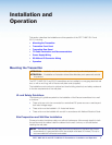
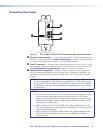
6. Feed the twisted pair cables and, if applicable, the power cables through the opening
and through the wall box punch-out holes, securing them with cable clamps to provide
strain relief.
NOTES:
• In order to fit in the wall box, the twisted pair cables and RJ-45 connectors
should not have a boot installed.
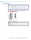
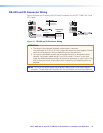
• One power supply can power both the transmitter and compatible receiver, so
only one unit needs a power supply (see Power Supply Wiring on page 11).
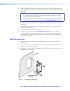
7. Trim back and insulate exposed cable shields with heat shrink to reduce the chance of
short circuits.
To prevent short circuits, the outer foil shield can be cut back to the point where the
cable exits the cable clamp.
8. Connect the cables to the rear of the unit.
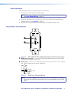
9. Connect front panel devices (see Transmitter Front Panel on the next page for
connector details), restore the power supply, and test the transmitter and receiver
system. Make any cabling adjustments before final installation, as the cables will be
inaccessible afterwards.
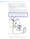
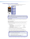
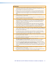
Mud Ring Installation
1. Using the mud ring as a guide, mark the edges and cut out the material within the
marked area.
2. Insert the mud ring into the opening and rotate and secure the locking arms with the
supplied screws shown in figure 4.
3. Follow steps 6 through 9 of Site Preparation and Wall Box Installation above, and Final
Installation on the next page.
Wall
Wall Mounting
Bracket
Figure 4. Installing the Mud Ring