


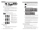
RGB/Component (HDSDI-ACR 100) or RGB/YUV (SDI-
AVR 100) switch — Set this switch to the Off position to
output RGB video. Set the switch on for component video.
Bi/tri-level switch (HDSDI-ACR 100 only) — Set this
switch to the On position to output tri-level sync on the
component video output. Set the switch off for bi-level
sync.
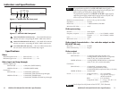
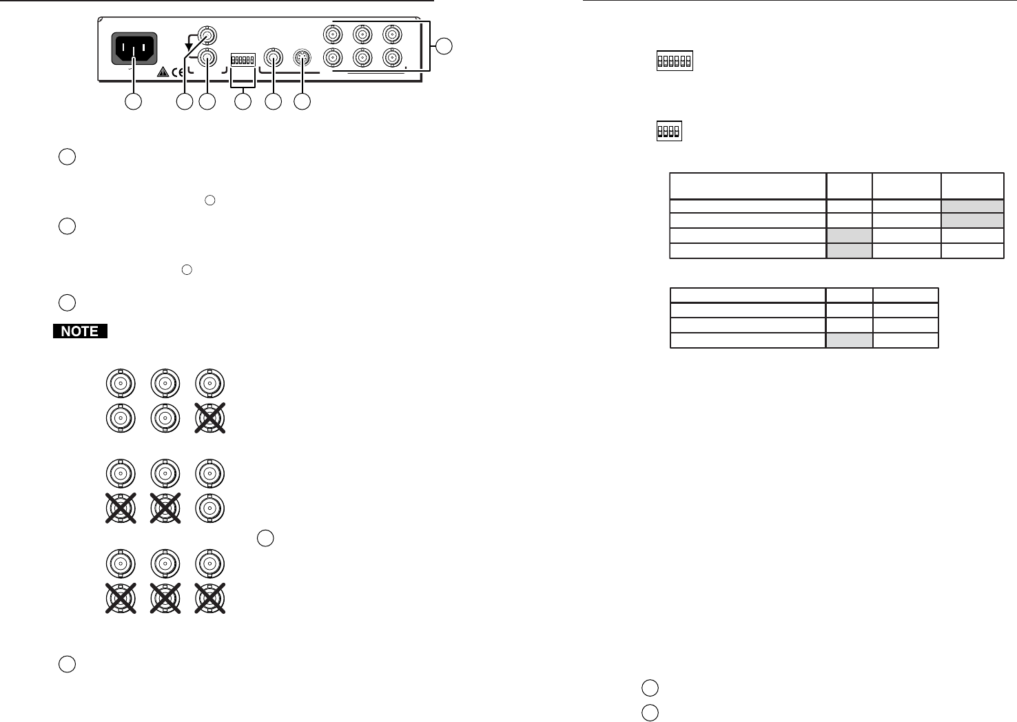
HDSDI-ACR 100 switch configuration
Output video format SOG
RGB/
Component
Bi/tri-level
RGBHV/RGBS Off Off Either
RGsB On Off Either
Y, R-Y, B-Y w/ bi-level on Y Either On Off
Y, R-Y, B-Y w/ tri-level on Y Either On On
SDI-AVR 100 switch configuration
Output video format SOG RGB/YUV
RGBHV/RGBS Off Off
RGsB On
Either
Off
Y, R-Y, B-Y On
Set Up switch (SDI-AVR 100 only) — Set this switch to the On position
to output an NTSC signal that is on the 7.5 IRE pedestal. Set the
switch off to return the signal to the normal level.
Beta switch (SDI-AVR 100 only) — Set this switch to the On position to
set the color level of the YUV output to the Betacam level. Set the
switch off to restore the YUV output to the normal level. If a
Betacam signal is input, the switch should be set to On to output
the Betacam format. Otherwise, the output will be NTSC or PAL.
Color Bars switch (SDI-AVR 100 only) — Set this switch to the On
position to output NTSC or PAL color bars. Set the switch off for
the converted video input.
NTSC/PAL switch (SDI-AVR 100 only) — Used in conjunction with
the Color Bars switch only, set this switch to the On position to
output PAL color bars. Set the switch off for NTSC color bars.
Front Panel Indicators
All indicators are on the front panel. Figure 5 and figure 6 show
HDSDI-ACR 100 and SDI-AVR 100 indicators.
1
Power LED — The Power LED indicates that power is on.
2
720P LED (HDSDI-ACR 100 only) — The 720P LED indicates that
the converter is outputting the HDTV 720P video format.
SOG
RGB/YUV
SET UP
BETA
COLOR BARS
NTSC/PAL
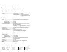
100-240V 50/60 Hz 0.2A
SDI INPUT OUTPUTS
IN
OUT
COMPOSITE
OUTPUT
S-VIDEO
OUTPUT
R/R-Y G/Y B/B-Y
HVS
ON
OFF
21 36 47
5
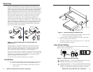
Figure 4 — SDI-AVR 100 rear panel
3
Composite Output connector (SDI-AVR 100 only) — Connect a
composite video display device to this BNC connector. This
output is available whenever an active SDI signal is applied to the
SDI input connector,
1
.
4
S-video Output connector (SDI-AVR 100 only) — Connect an
S-video device to this 4-pin mini DIN connector. This output is
available whenever an active SDI signal is applied to the SDI
input connector,
1
.
5
RGB/component video output connectors
Ensure that the rear panel DIP switches are in the correct
configuration (see Rear Panel Controls).
RGBHV video connection —
Connect to five BNC connectors
as shown.
RGBS video connection —
Connect to four BNC connectors
as shown.
RGsB and component video
connection — Connect to three
BNC connectors as shown.
6
AC power connector — Plug a
standard IEC power cord into
this connector to connect the
converter to a 100 to 240VAC, 50
Hz or 60 Hz power source.
Rear Panel Controls
7
DIP switches
SOG switch — Set this switch to the On position to output sync-
on-green for RGB video (RGsB). Set the switch off for
RGBHV or RGBS video.
R/R-Y G/Y B/B-Y
HVS
R/R-Y G/Y B/B-Y
HVS
R/R-Y
RGBHV
Video
RGBS
Video
RGsB or
Component
Video
G/Y B/B-Y
HVS
HDSDI-ACR 100 and SDI-AVR 100 • Installation and Operation 5HDSDI-ACR 100 and SDI-AVR 100 • Installation
Installation
4
SOG
RGB/YUV
SET UP
BETA
COLOR BARS
NTSC/PAL
ON
OFF
SOG OFF/ON
RGB/COMPONENT
BI/TRI-LEVEL
SPARE
ON
OFF