


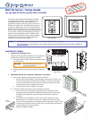
MLC 62 EU and MLC 62 MK • Setup Guide (Continued)
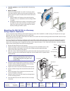
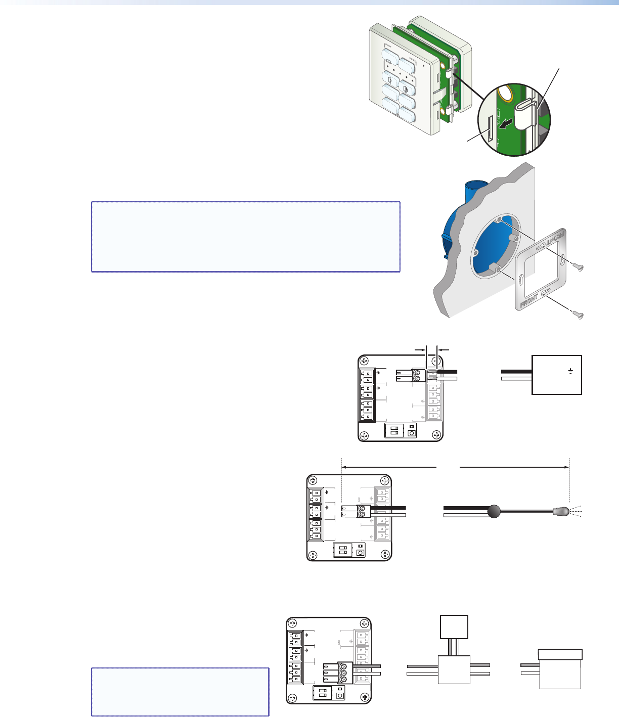
c. Reattach or replace the faceplate as follows (see the illustration
at right):
i. Making sure that both the MLC and the faceplate are
upright, hold the MLC with its circuit board against the
back of the faceplate, aligning the two tabs on each side of
the MLC with the two slots on each side of the faceplate.
ii. Each tab has a ridge that must snap into a slot on the side
of the MLC. Press the MLC into the faceplate until the
ridges on all four tabs snap into place.
3. Attach the metal mounting bracket to the junction box.
a. Place the metal bracket on the electrical box, aligning the slotted holes in
the bracket with the round holes on the box.
NOTE: To keep the MLC securely in place and prevent it from being
easily pulled from its mounting, ensure that the side of the
bracket with the word “Front” engraved on it faces out
(away from the electrical box). If you want to be able to
remove the MLC easily from its mounting, attach the bracket
with “Front” facing inward, toward the junction box.
b. Insert two of the included screws in the slots at the top and bottom of the
bracket as shown at right.
c. Tighten the screws to secure the bracket to the mounting surface.
4. Connect the cables to the MLC rear panel ports.
Attach the cables and IR emitters to the rear panel of the MLC
and to the display device or switcher as required.
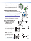
z Port A RS-232: Connect a display device or
switcher to this serial port to control the device via
RS-232 (see the illustration at right).
z Port B IR/S: Connect a display device, switcher,
or up to two IR emitters to this port (see the
illustration at right). You can configure this port
for either serial or IR communication using the
MLC 60 Series Configuration Program.
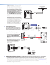
z Relay ports: The relay ports provide
connections for two relays. Connect one
or two devices (such as a low-voltage
controller and a motorized screen, shown
in the example at right) to this port. The
relay ports are normally open and rated
for 24 VDC, 1 A).
NOTE: If you use both relay ports,
connect the ground wires
of both devices to common
pin 3.
2
VOLUME
DISPLAY
PC
VIDEO
OFF
ON
MUTE
LAPTOP
Ridge on tab
snaps into slot
.
Slot
MLC RS EU or MK Rear Panel
RELAYS
N/O
PWR
12 V
0.4 A max
HOST/
CONFIG
DIGITAL
INPUT
+
Tx
Rx
1
Tx
Tx/
IR
1
2
C
12
R
PORT A
RS-232
PORT B
IR/ S
50'
(15 m max.)
Ground
IR Signal
IR Emitter
RELAYS
N/O
PWR
12 V
0.4 A max
HOST/
CONFIG
DIGITAL
INPUT
+
Tx
Rx
1
Tx
Tx/
IR
1
2
C
12
R
PORT A
RS-232
PORT B
IR/ S
Ground
Ground
Signal
110/220 V
MLC 62 RS EU or MK Rear Panel
Low Voltage
Screen Control
Motorized
Screen
Power
Supply
MLC RS EU or MK Rear Panel
RELAYS
N/O
PWR
12 V
0.4 A max
HOST/
CONFIG
DIGITAL
INPUT
+
Tx
Rx
1
Tx
Tx/
IR
1
2
C
12
R
PORT A
RS-232
PORT B
IR/ S
Ground
Transmit (Tx)
Ground ( )
Receive (Rx)
Display Device
3/16”
(5 mm) Max.
Electrical
Junction Box
Metal Bracket