


18
Installation
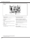
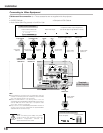
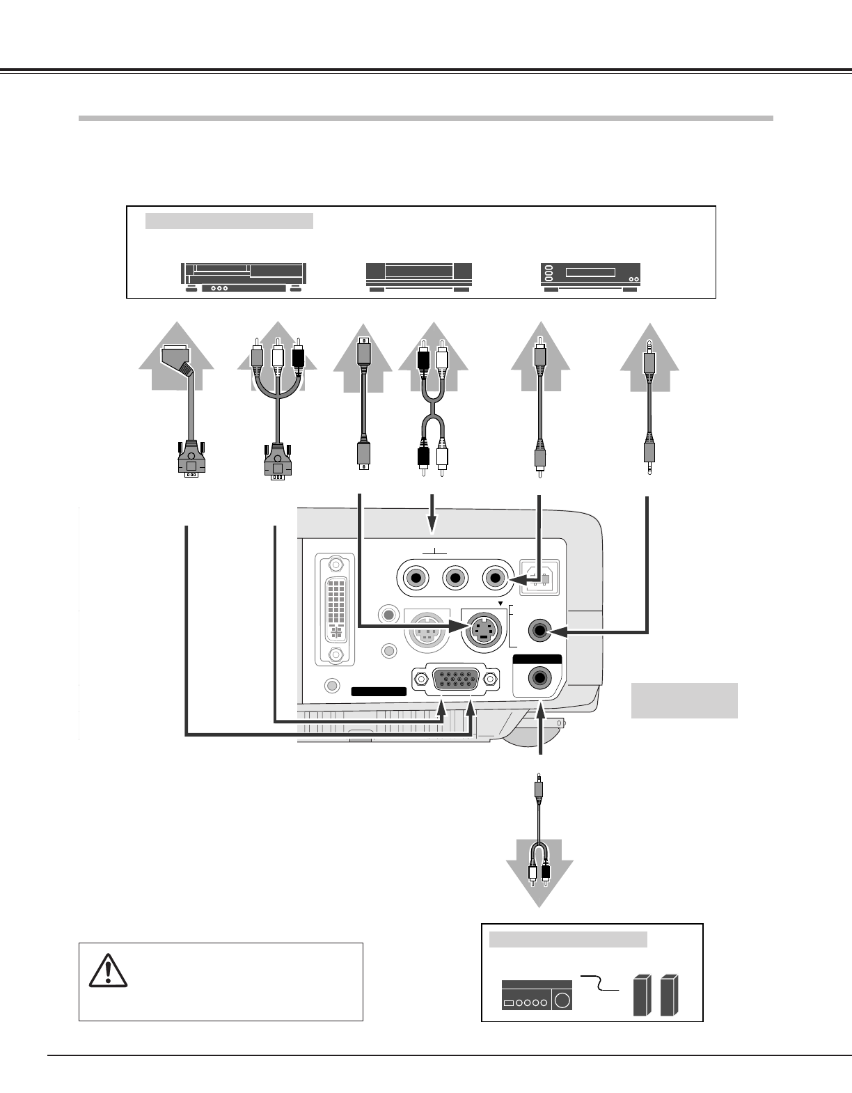
Connecting to Video Equipment
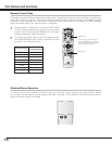
COMPUTER IN 1
DVI - I
MONITOR OUT
S-VIDEO
COMPUTER IN 2 /
COMPONENT IN /
COMPUTER /
COMPONENT
AUDIO IN
AUDIO IN
R VIDEOL
USB
SERVICE PORT
RESET
MCI
(MONO)
(VARIABLE)
AUDIO OUT
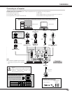
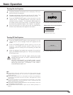
Video Source (example)
Video Cassette Recorder
Video Disc Player
S-VIDEO
Cable
✽
Audio Amplifier
Audio Speaker
(stereo)
Audio Cable
(Stereo)
✽
Terminals
of the Projector
S-VIDEO
Output
Audio Input
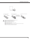
• Video Cable (RCA x 1) ✽
• S-VIDEO Cable ✽
• Audio Cables (Mini Plug (stereo) x 2 or RCA x 2) ✽
• Scart-VGA Cable ✽
• Component-VGA Cable ✽
NOTE :
When connecting the cable, the power
cords of both the projector and the
external equipment should be
disconnected from AC outlet.
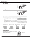
Audio Output
Audio Cable
(Stereo) ✽
External Audio Equipment
AUDIO INS-VIDEO VIDEO
AUDIO OUT
Component video output equipment.
(such as DVD player or high-definition TV source.)
Component Video Output
(Y, Pb/Cb, Pr/Cr)
Composite Video Output
Video Cable
(RCA x 1) ✽
Scart-VGA
Cable ✽
RGB Scart
21-pin Output
Cables used for connection (✽ = These accessories are not supplied with this projector.)
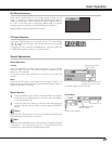
COMPUTER IN 2 /
COMPONENT IN/
MONITOR OUT
Component-
VGA Cable ✽
Audio Cable
(RCA x 2) ✽
Audio Output
(R, L)
AUDIO IN
COMPUTER IN 2 /
COMPONENT IN/
MONITOR OUT
NOTE
● The S-VIDEO jack has priority over the VIDEO jack under the
condition of connecting both the S-VIDEO jack and the VIDEO
jack when selecting AUTO in the Input Menu.
● Select COMPUTER 2 in the Setting Menu when the
COMPUTER IN 2/COMPONENT IN/MONITOR OUT terminal is
used as RGB Scart 21-Pin video input or Component video
input. (See “Terminal” on page 39.)
● Input sound to the COMPUTER/COMPONENT AUDIO IN
terminal when using the COMPUTER IN 2/COMPONENT
IN/MONITOR OUT terminal as input.