5
Model VC-8 Owner’s Manual
VR800: Asynchronous mode
VR800: Synchronous mode
Other recorder: Internal mode
Other recorder: External mode
CLOCK switch
INT (44.1kHz)
CLOCK switch
WORD or OPTICAL
VR800 (or recorder): Master
VC-8: Master
VR800 (or recorder): Slave
VC-8: Slave
VR800 (or recorder): Slave
VC-8: Slave
VR800 (or recorder): Slave
VC-8: Slave
Recorder
VC-8
Connecting Examples
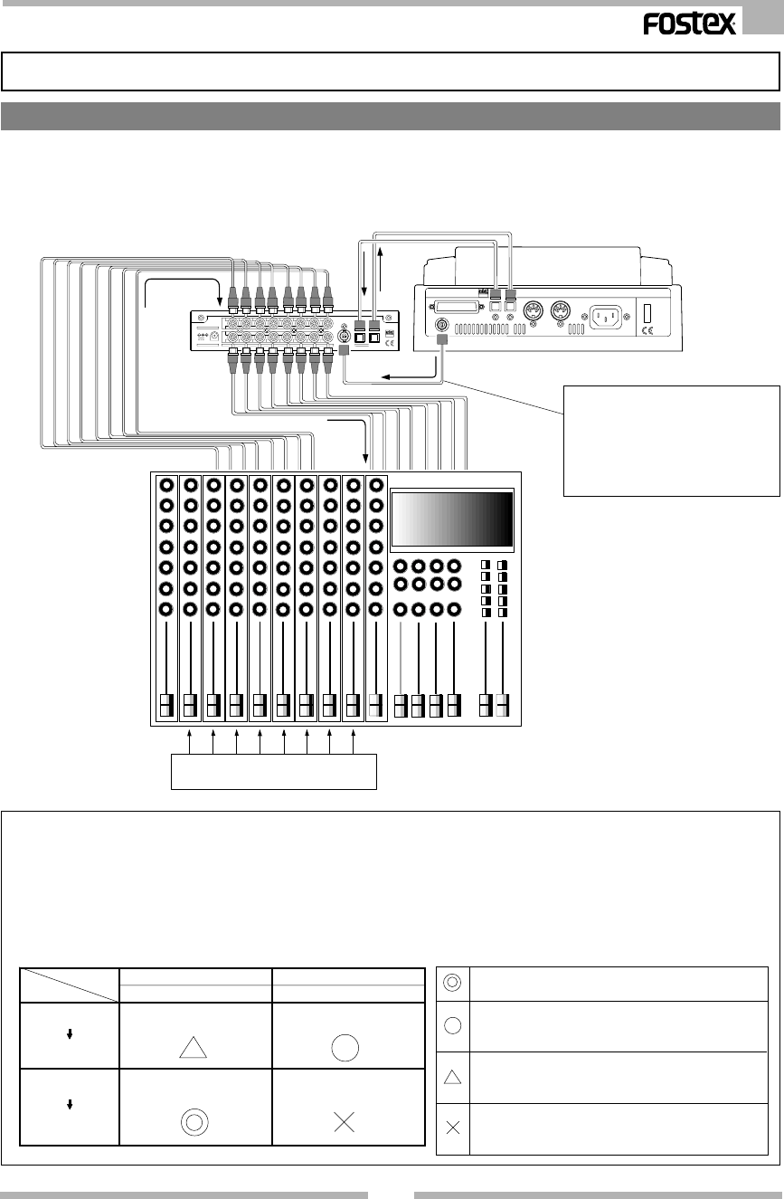
Example at operating it as the ADAT-ANALOG converter
The following connecting schematic is an example of locating the VC-8 between an analog mixer
with 8 TAPE IN - 8 BUS OUT (or GROUP OUT) and the VR800 (digital multitrack recorder). In this
system, the 8 BUS output from the analog mixer is converted to adat digital signals and the signals of
channels 1~8 can be recorded on tracks 1~8 of the VR800.
Note:
When connecting to a
digital recorder with WORD OUT
such as VR800, it always must
be connected to WORD IN of the
VC-8 and used by input of
WORD clock.
AD-12A ONLY
IN
OUT
OPTICAL
54321
54321
ANALOG
76
768
8
12V
DC IN
BUSS OUT (GROUP OUT) 1~8
TAPE IN 1~8
Analog Mixing Console
OPTICAL
POWERAC INOUT IN
MIDI
OUTSCSIWORD OUT
DATA IN
VR800
VC- 8
DATA OUT
WORD IN
WORD OUT
DATA IN
DATA OUT
Note: When the digital inputs and outputs of the VC-8 and VR800 (or another digital recorder) are connected
as shown in above connecting schematic, be sure to set one side as the clock master and the other as the
clock slave.
In other words, if the VC-8 had been set as the master, then VR800 (or another digital recorder) must be set
as the slave, or if in the reverse situation whereas VC-8 had been set as the slave, then VR800 (or another
digital recorder) must be set as the master. The most recommended setting at using the VC-8 is to establish
the digital recorder as the master and the VC-8 as the slave as shown in table below.
Sound sources
The most recommended setting. Furthermore, if the
WORD clock can be input, then WORD must be input.
This setting is employed if the recorder (general DAT and
MD) has an internal clock and thus cannot accept digital
signals.
Mutual exchanged of digital signals between the equip-
ment is possible by this setting, but deterioration of sound
quality is unavoidable.
This setting cannot be used. A digital loop will be created
in general type DAT and MD and thus will not operate
correctly.


