


8
EN
I
NTRODUCTION
Attaching a Wall Mount Bracket (sold separately)
The following is a description of the method for attaching a wall mount to this unit.
When performing this operation, refer to the instruction manual included with the wall mount kit.
#
CAUTION
• Any damage caused by incorrectly attempting to mount this unit is not covered under the terms of the manufacturers warranty.
• This unit may be used only with CL-M manufactured by OMNIMOUNT SYSTEMS.
• Use with other wall mounts may result in instability causing possible injury.
You need the following wall mount kit for this unit.
Medium Cantilever Flat Panel Mount
Model number: CL-M
For more information, please visit OMNIMOUNT SYSTEMS website at www.omnimount.com/consumer/Default.aspx
5
1
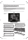
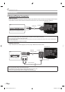
Spread a thick and soft cloth over a table. Place this
unit face down onto it. Make sure not to damage the
screen. At least two people are required at this step.
Note:
• Make sure to use a table which can support the weight of
this unit and is larger than this unit.
• Make sure the table is in a stable location.
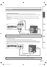
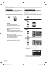
2
Unscrew the M4 screws indicated by
1
and remove the
stand. Please be careful with the unit after you remove
the stand.
Note:
• The M4 screws and stand you have removed are necessary
for reattachment at a later date. Make sure to keep them in
a safe place.
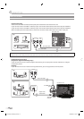
3
Unscrew the M4 screws indicated by
2
an
d attach the
monitor plate to this unit using the M4×16mm screws.
You do not need to use the lock washers for mounting
this unit.
Note:
• Only use the screw holes indicated by
2
for mounting this
unit.
• For instructions on how to attach the monitor plate, refer
to the instruction manual included with the wall mount kit.
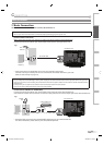
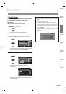
4
Attach this unit to the wall. At least two people are
required at this step.
Note:
• Refer to the instruction manual included with the wall
mount kit when securing this unit to the wall.
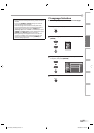
* If you want to attach the stand of this unit again,
insert the stand slowly as illustrated below and drive
M4 screws in the 4 threaded holes (
1
).
2
rear of this unit
1
1
stand
* 1 and 2 indicate the
position of the screw holes
on this unit.
1
A71F6UH_FLX3220F_EN.indd 8A71F6UH_FLX3220F_EN.indd 8 2007/08/08 14:53:062007/08/08 14:53:06