


8
En
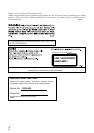
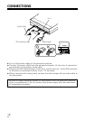
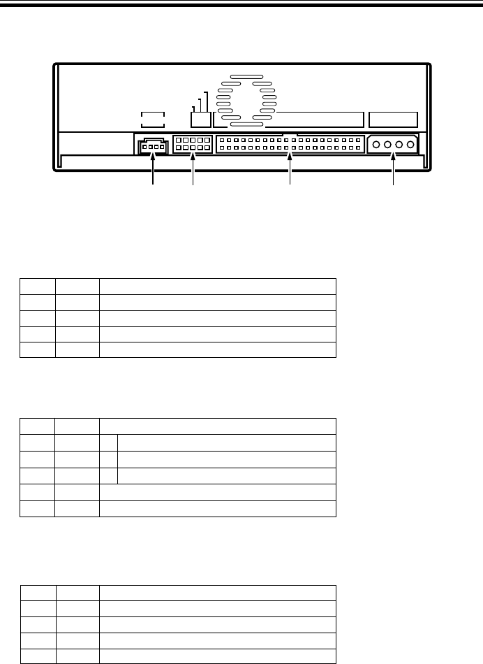
INTERFACE
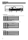
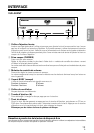
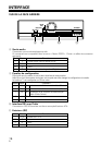
REAR VIEW
Pin Name Function
1 L Left channel audio output.
2 G Ground.
3 G Ground.
4 R Right channel audio output.
Pin Name Function
1 MA on The drive is used in master mode.
2 SL on The drive is used in slave mode.
3 CS on Using Cable Select function.
4 Reserved.
5 Reserved.
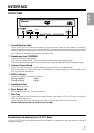
8 Audio Output
This is a connector for output of analog audio.
This connector is compatible with `Molex 70553`, choose a suitable connection cable.
Pin Name Function
1 +12 Power supply input for DC +12 V.
2 G Ground.
3 G Ground.
4 +5 Power supply input for DC +5 V.
9 Device Configuration Jumper
Switch becomes ON when short socket is put.
Make sure the power of the drive is off before changing jumper setting.
Pin # 1 is ON at the time of shipping from the plant.
0 Host IDE Interface
This is a 40 pin I/O connector according to the ATA specifications.
- DC Input
8 9 -0
ANLOG AUDIO
CABLE SELECT
SLAVE
MASTER
5V G G 12V
ALS
M
40
39
2
1
SC
IDE INTERFACE
DC INPUT