5
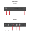
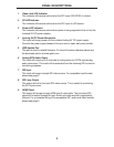
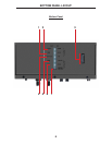
1 Video Lock LED Indicator
This indicator will become active when the SDI input (SD/HD/3G) is locked.
2 3G LED Indicator
This indicator will become active when the SDI input is a 3G source.
3 Power LED Indicator
This indicator will become active when power is being supplied to the unit via the
included 5V DC power adapter.
4 Locking 5V DC Power Receptacle
This input will accept power via the included locking 5V DC power supply.
Connect the power supply between this input and an open wall power socket.
5 USB Update Port
This port is used to update fi rmware. For current fi rmware releases please see
the download section at www.gefen.com.
6 Analog RCA Audio Ouput
This input will output up to 2 channels of analog audio via 2 RCA style analog
audio connectors. This audio will be extracted from the incoming SDI source for
monitoring purposes.
7 SDI Input
This input will accept a single SDI video source. For acceptable input formats
please see page 2.
8 SDI Loop Output
This output will mirror the input SDI video source. This is useful for monitoring
the SDI input source.
9 HDMI Ouput
This output will accept a single HDMI type A male cable. The converted SDI
signal will be output through this port. Audio and video are both supported by
this port. For a complete listing of the acceptable SDI, audio and video formats
please see page 2.
PANEL DESCRIPTIONS


