


Setup
8 312761B
Setup
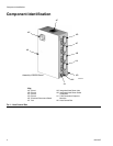
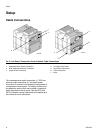
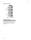
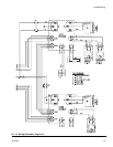
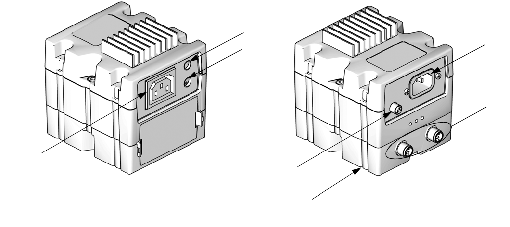
Cable Connections
1 Overtemperature Switch Connection
2 RTD Temperature Sensor Connection
3 Output Power Connection
4 DC Output Connection
5 Input Power Connection
6 CAN Connections
7Base
The overtemperature switch connection (1), RTD tem-
perature sensor connection (2), and output power
connection (3) connect to the respective components of
a temperature control option. The display module must
be updated to specify which zone number is used with
which temperature control option. See the PR70 and
PR70v Operation manual referenced at the beginning of
this manual for more information.
F
IG. 5: Low Power Temperature Control Module Cable Connections
1
2
3
4
5
6
7
ti12356a
ti12357a