


2
Figure 1
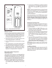
REMOTE RECEIVER
Important: The remote receiver should be posi-
tioned close to front in right or left corner.
The remote receiver is powered by 110-120VAC. It plugs
into a standard polarized duplex receptacle.
Locating Receiver and Operating Functions
This remote receiver can be positioned under the fire-
box in the control compartment of the fireplace if ambi-
ent temperatures do not exceed 170
0
F. This system is
designed to remotely operate the gas valve.
INSTALLATION INSTRUCTIONS
Installing Electrical Service to the Junction Box
WARNING: TURN ELECTRICAL POWER OFF
AT THE CIRCUIT BREAKER BEFORE BEGIN-
NING THIS INSTALLATION.
NOTE: Some appliances do not have a cover plate.
Instead, there is a hole through which the Romex clamp
is attached to the outer wrap.
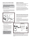
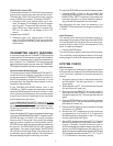
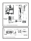
1. Remove the electrical cover plate from the lower
side of the fireplace. Remove the knock-out from
the plate and attach the Romex clamp (screws to
the outside) (see Figure 1).
2. Feed the electrical service wires
through the Romex clamp and secure
the wires to the clamp.
3. Using the wire nuts provided, connect
the service wires to the junction box.
The black wires to the black service
wire, the white wires to the white ser-
vice wire, and the service ground wire
to the ground stud of the junction box.
4. Re-attach the cover plate to the out-
side of the fireplace.
WARNING: LEAVE ELECTRICAL
POWER OFF AT THIS TIME. DO
NOT RESTORE POWER UNTIL
THE REMOTE CONTROL SYSTEM
IS COMPLETELY INSTALLED.
ACCESS HOLE
COVER
PLATE
110 VAC
SERVICE
RECEIVER WIRING INSTRUCTIONS
Incorrect wiring connections WILL cause damage to the
gas valve or electronic module operating the gas appli-
ance and may also damage the remote receiver.
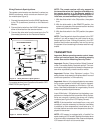
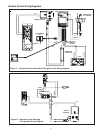
Wiring Millivolt Valves
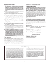
Connect the remote receiver by connecting each of the
two wires leading from the remote receiver to either of
the two wire TH terminals on the gas valve (see Fig-
ure 2). Normally it does not matter which wires go to
which terminal.
Figure 2. Wiring Millivolt Valves
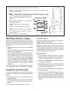
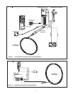
Alternative Wiring for units with a wall switch
Disconnect the wall switch wire from the TH terminal on the valve and
connect this wire to male connector supplied on the receiver. Con-
nect remaining female connector from receiver to the TH terminal on
the valve.
REMOTE
RECEIVER
THERMOPILE/
PILOT LIGHT
TERMINAL BLOCK
ON MILLIVOLT GAS VALVES
TH
TP
WALL
SWITCH
TP TH