


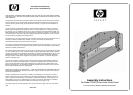

FOR YOUR SAFETY, PLEASE FOLLOW THESE PRECAUTIONS:
! ALWAYS REMOVE THE TV AND OTHER EQUIPMENT FROM THE FURNITURE PRIOR TO MOVING THE ASSEMBLED UNIT.
! BE CAREFUL
WHEN MOVING THE ASSEMBLED FURNITURE AFTER THE GLASS SHELF HAS BEEN INSTALLED,
AND/OR WHEN
THERE IS EQUIPMENT
LOCA
TED ON
THE FURNITURE AS THIS MAY CAUSE THE SHELF TO BECOME
UNSECURED AND FALL.
! WHEN IN USE, THIS FURNITURE MUST BE PLACED ON A FLAT, SOLID AND LEVEL SURFACE.
! DO NOT
LEAN ON
THE
TV WHEN IT
IS ON
THE TV STAND.
! DO NOT
CLIMB OR STEP
ON
THE ST
AND.
! DO NOT BANG OR PLACE YOUR OWN WEIGHT ON THE GLASS SHELF.
! DO NOT
PLACE ITEMS ON
THE SHEL
VES WHICH EXCEED THE MAXIMUM WEIGHT LIMITS OF 200 LBS. FOR TOP SHELF
AND 50 LBS. FOR GLASS SHELF
Assembly Instructions
NOTE: TWO PEOPLE ARE RECOMMENDED TO ASSEMBLE THIS TABLE.
A. INSERT two Cam Locks (8) into each of the Side Support
Panels (6). INSERT five Cam Lock Connector Bolts (9) into
the Left Front Panel (4) and Right Front Panel (5).
B.
INSERT a Glass Shelf Support Pin (11) into the center hole
of each Side Support Panel (6).
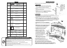
C.
ATTACH each Front Panel (4 & 5) to each Side Support
Panel (6) as shown in Fig. 1.
TIGHTEN Cam Locks (8) with
Philips Screwdriver, DO NOT OVERTIGHTEN.
Fig. 1
4,5
9
1. Side Assembly
6
8
11
2. Table Assembly
A. PLACE the Bottom Shelf (1) on a soft flat surface with the pre-assembled feet
facing up. INSERT four Cam Locks (8) into the large holes. Make sure the thread openings of the
Cam Locks face toward the outside edge of the Bottom Shelf (1).
B.
CAREFULLY TIP the Bottom Shelf (1) on the front (longer) edge so that the underside is facing
away from you. ALIGN the edges of the Side Panels (6) and Bottom Shelf and INSERT the Cam
Lock Connector Bolts (9) into the Cam Locks (8). SECURE the Side Panels (6) to the Bottom Shelf
by tightening the Cam Locks with the philips screwdriver, DO NOT OVERTIGHTEN.
INSERT two
50mm Screws (10) through the predrilled holes in the Bottom Shelf and
into the Side Panels (6) and tighten.
C.
CAREFULLY TIP the unit upside down and SECURE the
Rear Support Panel (3) to the table bottom using four Screws
(10).
D.
CAREFULLY TIP the partially assembled table over so that
it is sitting upright on the floor. PLACE two Shelf Support
Pins (11) into the holes in the rear panel as shown in
Fig. 2. Make sure the rubber pads are facing up.
E.
PLACE the Glass Shelf (7) into the partially
assembled table and onto the four Shelf
Support Pins (11) as shown in Fig. 2.
F.
PLACE the Top Shelf (2) onto partially
assembled table. INSERT the Cam Lock
Connector Bolts (9) in the Front Panels
(4,5) into the Cam Locks (8) in the Top
Shelf and turn Cam Locks to tighten. DO
NOT
OVER
TIGHTEN.
SECURE T
op Shelf
using eight 50mm Screws (10).
G.
INSERT eight
Plastic Screw Caps (13)
over the Screws (10) which were inserted
into the Top Shelf (2), as shown in Fig. 2.
FOR
YOUR SAFETY
, SECURE
THE
TV
T
O
THE
TABLE FROM BENEATH THE THE TOP SHELF
USING 4 OF
THE SUPPLIED 30MM BOL
TS (P
AR
T
#12)
NOTE:
THE MIDDLE GLASS SHELF (7) CAN NOT
BE REMOVED
ONCE
THE TOP SHELF (2) IS SECURED, BUT IT CAN SHIFT OR TIP
FOR
W
ARD WHEN
THE
T
ABLE IS MOVED OR IF THE SHELF SUPPORT PINS (11)
ARE NOT
PLACED SECURELY IN THEIR HOLES WITH THE RUBBER PADS FACING
UPWARDS. ALWAYS PLACE HEAVIEST COMPONENTS ON LOWER SHELF.
2
7
3
4
1
5
6
6
11
9
10
10
10
13
8
8
8
8
Fig. 2
Parts List
34mm Cam Lock Connector Bolt
50mm Screw
30mm Screw
Cam Lock
Glass Shelf Support Pin
Plastic Screw Caps
Left & Right Front Panels
Side Support Panels
Rear Support Panel
with Cable Management
Top Shelf
Glass Shelf
Bottom Shelf
PART #
Q
UANTITY
P
ART DESCRIPTION
9
16
4
10
10
4
8
2
2
1
1
1
1
10
12
8
2
7
1
11
13
4 (Left)
5 (Right)
6
3
REQUIRED
TOOLS
Allen Wrench
Philips Screwdriver