


Rev. 1.0, 07/01, page 133 of 372
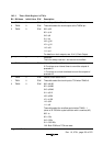
10.3.1 Timer Mode Register A(TMA)
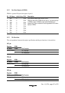
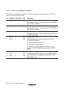
Bit Bit Name Initial Value R/W Description
7
6
5
TMA7
TMA6
TMA5
0
0
0
R/W
R/W
R/W
Clock Output Select 7 to 5
These bits select the clock output at the TMOW pin.
000: φ/32
001: φ/16
010: φ/8
011: φ/4
100: φ
w
/32
101: φ
w
/16
110: φ
w
/8
111: φ
w
/4
For details on clock outputs, see 10.4.3, Clock Output.
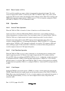
4 − 1 − Reserved
This bit is always read as 1 and cannot be modified.
3 TMA3 0 R/W Internal Clock Select 3
0: Functions as an interval timer to count the outputs of
prescaler S.
1: Functions as a clock-time base to count the outputs of
prescaler W.
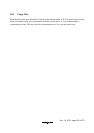
2
1
0
TMA2
TMA1
TMA0
0
0
0
R/W
R/W
R/W
Internal Clock Select 2 to 0
These bits select the clock input to TCA when TMA3=0.
000: φ/8192
001: φ/4096
010: φ/2048
011: φ/512
100: φ/256
101: φ/128
110: φ/32
111: φ/8
These bits select the overflow period when TMA3 = 1
(when a 32.768 kHz crystal oscillator with is used as φW).
000: 1s
001: 0.5s
010: 0.25s
011: 0.03125s
1XX: Both PSW and TCA are reset
Legend X: Don't care.