VR8304 INTERMITTENT PILOT COMBINATION GAS CONTROL
69-0625—03 4
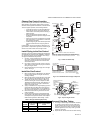
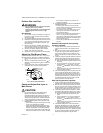
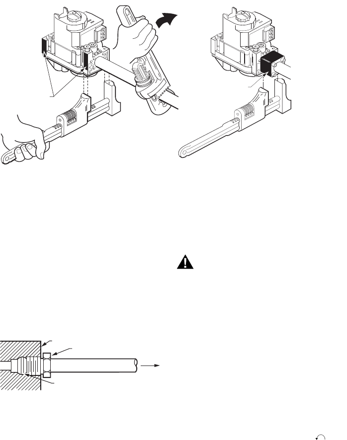
Fig. 5. Proper use of a wrench on a gas control with and without flanges.
3. Unscrew compression titling from the pilot outlet
(Fig. 4).
4. Slip the compression fitting over the tubing and
slide out of the way.
5. Push the tubing into the pilot gas tapping on the
outlet end of the control until it bottoms. While hold-
ing tubing all the way in, slide compression flitting
into place and engage threads—turn until finger
tight. Then tighten one more turn with a wrench. Do
not overtighten. Refer to Fig. 6.
6. Connect other end of the tubing to pilot burner
according to the pilot burner’s manufacturer’s
instructions.
NOTE: When replacing a gas control, cut off old com-
pression fitting and replace it with the new com-
pression fitting provided on the gas control.
Never use the old compression fitting as it may
not provide a gas-tight seal.
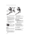
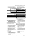
Fig. 6. Always use new compression fitting.
WIRING
Follow the wiring instructions furnished by the appliance
manufacturer if available or use the general instructions
provided below.
All wiring must comply with applicable electrical codes
and ordinances.
Disconnect power supply before making wiring connections
to prevent electrical shock or equipment damage.
1. Check the power supply rating on the gas control
and ensure it matches the available supply. Install
transformer, thermostat, and other controls as
required.
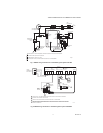
2. Connect the control circuit to the gas control termi-
nals. See Figs. 4 and 7 or 8.
3. Adjust the thermostat heat anticipator to 0.70 rating
stamped on valve operator.
STARTUP AND CHECKOUT
WARNING
Fire or explosion hazard. Can cause property
damage, severe injury, or death.
1. Do not force the gas control knob. Use only
your hand to turn the gas control knob. Never
use tools.
2. If the gas control knob will not operate by hand,
the gas control should be replaced by a
qualified service technician.
Gas Control Knob Settings
The gas control knob has two settings:
OFF—prevents pilot and main burner gas flow.
ON—permits gas to flow into the control body. Under
control of the thermostat and intermittent pilot module,
pilot and main burner gas flow is permitted.
NOTE: Gas controls are shipped with the gas control
knob in the ON position.
Turn on the System
Rotate the gas control knob counterclockwise to ON.
Turn on the Main Burner
Follow the instructions provided by the appliance
manufacturer or turn the thermostat up to call for heat.
APPLY WRENCH
FROM TOP OR
BOTTOM OF GAS
CONTROL TO
EITHER SHADED AREA
WHEN FLANGE IS NOT USED
APPLY WRENCH
TO FLANGE ONLY
WHEN FLANGE IS USED
M3079
GAS CONTROL
TIGHTEN NUT ONE TURN
BEYOND FINGER-TIGHT.
TO PILOT
BURNER
FITTING BREAKS OFF AND CLINCHES
TUBING AS NUT IS TIGHTENED.
M3076B


