


20
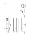
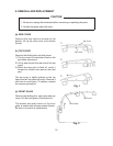
[d] SIDE FRAME
Remove the sliding door, side cover and top cover. Unbind the wiring on the side frame.
Remove the two screws securing the top frame and the top of the side frame. Lift the side
IUDPHRIIWKHERWWRP¿W
Fig. 3
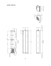
Fig. 5
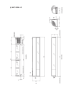
Fig. 4
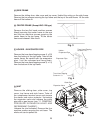
Truss Head Tapping
Screw 4 x 25
Truss Head Tapping
Screw 4 x 10
Holder -
Evaporator Pipe
Evaporator Pipe
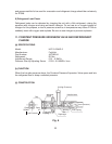
[e] CENTER FRAME (Except HNC-120 type)
Remove the two flat head machine screws
(black) securing the center frame to the rear
and the two machine screws securing the
center frame to the top frame. Tilt the center
IUDPHDQGUHOHDVHLWIURPWKH¿W
[f] HOLDER - EVAPORATOR PIPE
Remove the truss head tapping screw (4 x 25)
from the bottom of the top frame. Take off the
center frame. Be careful with the evaporator
pipe. It will be released and hang down.
Remove the truss head tapping screw (4 x 10)
from the bottom of the top frame.
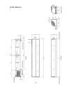
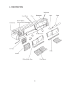
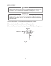
[g] UNIT
Remove the sliding door, side cover, top
cover, top frame and side frame. Take off
the compressor terminal cover and remove
the starter and motor protector. Uninsulate
the expansion valve and unbraze the outlet
pipe with a gas burner (see “11. CONSTANT
PRESSURE EXPANSION VALVE AND
REFRIGERANT CHARGE”).
8QEUD]HWKHMRLQWLQGLFDWHG5HPRYHWKHIRXU
machine screws securing the unit base. The
whole unit can be pulled out.
Outlet Pipe
Joint
Expansion Valve