


ii
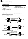
MISCELLANEOUS ITEMS
The following parts are additionally required for instal-
lation, but are not supplied with the AT-140.
Purchase these parts locally.
q AWG 14×4-conductor shielded cable
*Icom offers an optional OPC-1147
CONTROL CABLE
.
Length: 10 m; 32.8 feet
w 50 Ω coaxial cable
e PL-259 connectors
FEATURES
Matches all bands
The AT-140 matches any frequency on every HF ma-
rine band. For example, the tuner matches a 7 m; 23 ft
long-wire antenna across 1.6–30 MHz.
Full automatic tuning
Just push the [TUNE] switch on the transceiver, and
the AT-140 adjusts immediately to the minimum SWR
of any frequency on any HF marine band.
HF operation on any size ship
The AT-140 allows you HF operation where antenna
element length is restricted due to space.
Weather resistant
The AT-140 is housed in a durable, completely weather
resistant ASA case with a rubber gasket. The antenna
tuner can be conveniently installed both on the deck or
in the cabin near the antenna element.
Simple installation
Installation is simple. Just connect the control and an-
tenna cables. You never need to open the cover.
45 memories for shorter tuning time
To decrease the tune-up time, the AT-140 automatically
stores the matching conditions for up to 45 frequencies.
Re-tuning for a memorized frequency takes approx. 1
sec.
Super capacitor for memory backup
Even if the AT-140 is not used for approx. 1 week, the
built-in super capacitor backs up contents of the 45
memories.
Low power tune up
The AT-140 emits low output power during tuning. This
feature reduces the possibility of causing interference
to other stations.
Tuner through function
The tuner through function is built into the AT-140. This
function helps improve receiver gain, depending on the
antenna element length used, and operating fre-
quency.
TABLE OF CONTENTS
FOREWORD …………………………………………… i
IMPORTANT …………………………………………… i
EXPLICIT DEFINITIONS……………………………… i
PRECAUTIONS ……………………………………… i
SUPPLIED ACCESSORIES ………………………… i
MISCELLANEOUS ITEMS ………………………… ii
FEATURES …………………………………………… ii
TABLE OF CONTENTS ……………………………… ii
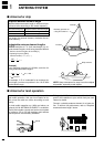
1 ANTENNA SYSTEM …………………………… 1–2
■ Antenna for ship ………………………………… 1
■ Antenna for land operation ……………………… 1
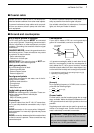
■ Coaxial cable …………………………………… 2
■ Ground and counterpoise ……………………… 2
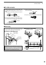
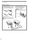
2 INSTALLATIONS ………………………………… 3–5
■ lnstallation outline………………………………… 3
■ Control cable……………………………………… 3
■ PL-259 connector………………………………… 4
■ Mounting ………………………………………… 4
■ Cable connections ……………………………… 5
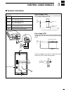
3 CONTROL CABLE SIGNALS ………………… 6–7
■ Terminal information …………………………… 6
■ Transceiver setting ……………………………… 7
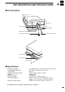
4 UNIT DESCRIPTION AND SPECIFICATIONS
………………………………………………………… 8
■ Unit description…………………………………… 8
■ Specifications …………………………………… 8