


4
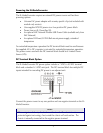
Cascading DC Power
If installing multiple IE–ModeConverters on a DIN rail,
you can use one DC input source and then cascade from
one DC terminal block to the next, until reaching the
maximum electrical current available.
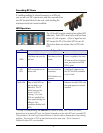
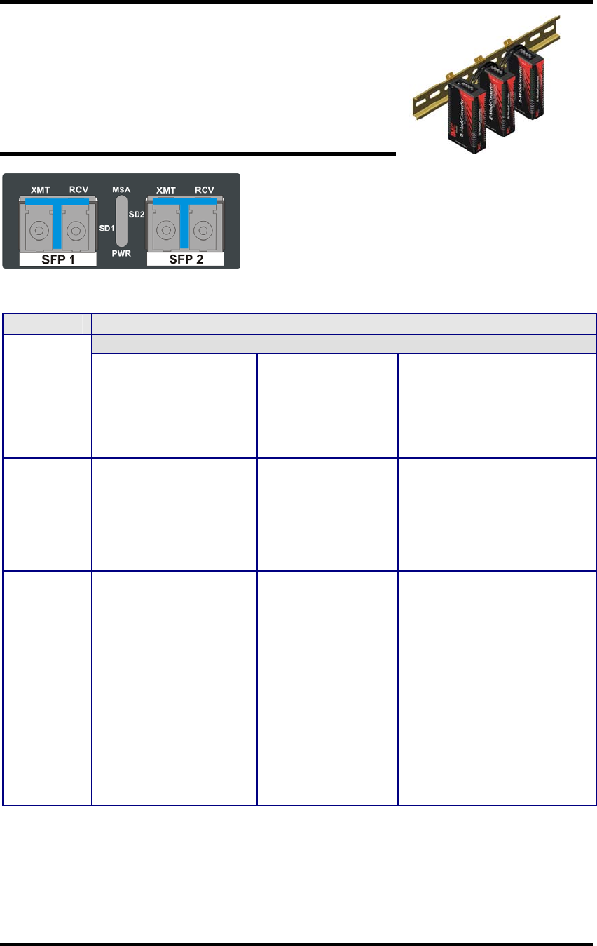
LED Operation
The IE–ModeConverter contains four status LED
indicators. Each LED is dual color and has three
states: off, red, or green. A loss of signal on one
SFP causes the TX of the other SFP to turn off.
This action does not activate the red TX Fault
LED.
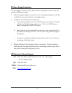
LED Color or State
Red OFF Green
PWR
Card does not pass the
self-test.
Unit does not have
power.
Power is applied to the card.
All internal self-test functions
must pass before the PWR
LED is green.
SD I
SD 2
LED transmitter has an
active fault.
No active fault on
transmitter.
LOS indication on
receiver.
Valid signal is detected by
the SFP and LED transmitter
is not in fault.
MSA LEDs One or both SFPs are
not installed or not
detected. The TX
inhibit must not be
active if a SFP is
missing.* Or, both
SFPs are installed, but
their speed settings are
different. This
condition disables both
SFPs.
N/A Indicates that both SFPs with
the same speed are securely
installed.
* To help in troubleshooting, the
Link Loss
(LL) feature is always ON. That is, if a LOS is
detected on an incoming SFP port, the Optical transmitter on the other SFP port is turned OFF.
This provides a Link Loss carry forward function to alert the device downstream of the existing
problem. This function is "ON" in both directions at the same time. The LL function is
inhibited if either SFP is not installed.