


Masterpage:Right
EN
9
Filename [HRS5950EU1-EN.fm]
Page 9 December 4, 2001 5:14 pm
INSTALLING YOUR NEW RECORDER
Basic Connections
It’s essential that your video recorder be properly
connected.
A
Check the contents.
Make sure the package contains all of the accessories
listed in “SPECIFICATIONS” on page 54.
B
Situate the recorder.
Place the recorder on a stable, horizontal surface.
C
Connect the recorder to TV.
The connection method you use depends on the type of
TV you have.
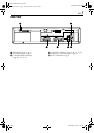
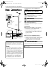
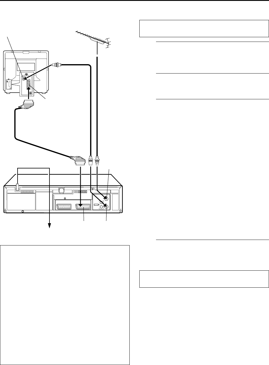
RF Connection
8
To connect to a TV with NO AV input connectors . . .
A
Disconnect the TV aerial cable from the TV.
B
Connect the TV aerial cable to the ANT. IN connector
on the rear panel of the recorder.
C
Connect the provided RF cable between the RF OUT
connector on the rear panel of the recorder and the
TV’s aerial connector.
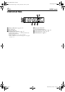
AV Connection
8
To connect to a TV with AV input connectors . . .
A
Connect the aerial, recorder and TV as per “RF
Connection”.
B
Connect an optional 21-pin SCART cable between the
L-1 IN/OUT connector on the rear panel of the
recorder and the TV’s 21-pin SCART connector.
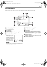
D
Connect the recorder to mains.
Plug the end of the mains power cord into a mains outlet.
Make AV connection if your TV has a 21-pin AV input
connector (SCART) in order to reduce the possibility of
interference. With AV connection, you can enjoy
stereo playback of video tapes if you are using a stereo
TV.
NOTES:
●
The L-1 IN/OUT connector accepts only a composite
signal (regular video signal) and delivers either a composite
signal (regular video signal) or a Y/C signal (a signal in
which the luminance and chrominance signals are
separated). If your TV’s 21-pin AV input connector (SCART)
is compatible with the Y/C signal, set “L-1 OUTPUT” to
“S-VIDEO” after the connection and the initial settings are
completed (
੬
pg. 30). You can obtain high-quality S-VHS
pictures. (For connection, be sure to use a 21-pin SCART
cable that is compatible with the Y/C signal.)
●
Set your TV to the VIDEO (or AV), Y/C, or RGB mode
according to the type of your TV’s SCART connector.
●
For switching the TV’s mode, refer to the instruction
manual of your television.
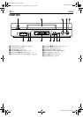
Aerial connector
Back of TV
21-pin SCART
connector
TV aerial
cable
RF cable
(provided)
21-pin SCART
cable
(not provided)
Mains power cord
Mains outlet
Back of recorder
L-1 IN/OUT
ANT. IN
RF OUT
THESE STEPS MUST BE COMPLETED BEFORE ANY
VIDEO OPERATION CAN BE PERFORMED.
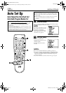
After the connection is completed, perform “Auto Set
Up” on page 10.
HRS5950EU1-EN.book Page 9 Tuesday, December 4, 2001 5:32 PM