


No.52026
A
V-14F3/AV-1435
A
V-1435EE/AV-1435TEE
A
V-14FMT3/AV-1438
A
V-14FMG3/AV-14FMG3
B
31
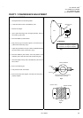
REPLACEMENT OF CHIP COMPONENT
!
CAUTIONS
1. Avoid heating for more than 3 seconds.
2. Do not rub the electrodes and the resist parts of the pattern.
3. When removing a chip part, melt the solder adequately.
4. Do not reuse a chip part after removing it.
!
SOLDERING IRON
1. Use a high insulation s oldering iron with a thin pointed end of it.
2. A 30w soldering iron is recommended for easily removing parts.
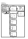
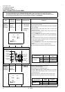
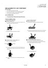
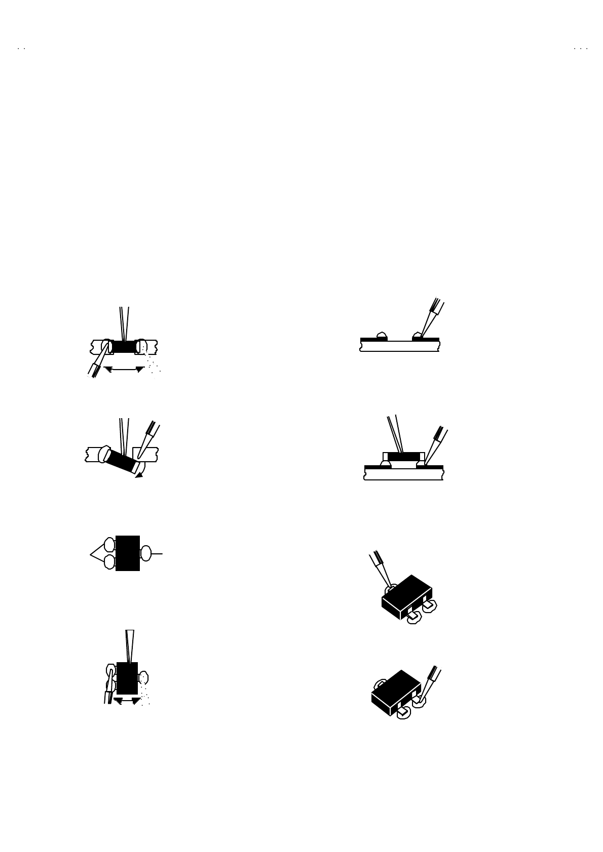
! REPLACEMENT STEPS
1. How to remove Chip parts
$
$$
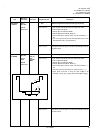
$ Resistors, capacitors, etc
(1) As shown in the figure, push the part with tweezers and
alternately melt the solder at each end.
(2) Shift with tweezers and remove the chip part.
$
$$
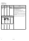
$ Transistors, diodes, variable resistors, etc
(1) Apply extra solder to each lead.
(2) As shown in the figure, push the part with tweezers and
alternately melt the solder at each lead. Shift and remove the
chip part.
Note : After removing the part, remove remaining solder from the
pattern.
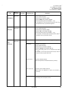
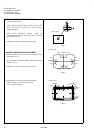
2. How to install Chip parts
$
$$
$
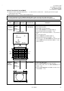
Resistors, capacitors, etc
(1) Apply solder to the pattern as indicated in the figure.
(2) Grasp the chip part with tweezers and place it on the s older.
Then heat and melt the solder at both ends of the chip part.
$
$$
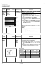
$ Transistors, diodes, variable resistors, etc
(1) Apply solder to the pattern as indicated in the figure.
(2) Grasp the chip part with tweezers and place it on the solder.
(3) First solder lead
A
as indicated in the figure.
(4) Then solder leads B and C.
SOLDER SOLDER
A
B
C
A
B
C