


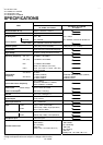


No. 52026
A
V-14F3/AV-1435
A
V-1435EE/AV-1435TEE
A
V-14FMT3/AV-1438
A
V-14FMG3/AV-14FMG3B
10
REPLACEMENT OF MEMORY ICs
1. MEMORY ICs
This model uses memory ICs. This memory IC data are for proper operation of the video and deflection circuits.
When replacing memory ICs, be sure to use ICs written with the initial values of data.
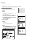
2. PROCEDURE FOR REPLACING MEMORY ICs
(1) Power off
Switch the power off and disconnect the power plug from the wall outlet.
(2) Replace ICs
Be sure to use memory ICs written with the initial data values.
(3) Power on
Connect the power plug into the wall outlet and switch the power on.
(4) Check and set SYSTEM CONSTANT SET
・
・・
・It must not adjust without adjustment signals.
1) Press the DISPLAY key and the PICTURE MODE key of the REMOTE
CONTROL UNIT simultaneously.
2) The SERVICE MENU screen of Fig. 1 will be displayed.
3) While the SERVICE MENU is displayed, again press the DISPLAY key and
PICTURE MODE key simultaneously, and the SYSTEM CONSTANT SET
screen of Fig. 2 will be displayed.
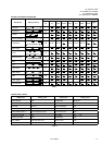
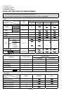
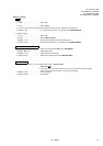
4) Check the setting values of the SYSTEM CONSTANT SET of T able 1 If the
value is different, select the setting item with the MENU ▼/▲key, and set
the correct value with the MENU - / + key.
5) Press the DISPLAY key twice, and return to the normal screen.
(5) Receive channel of setting
Refer to the OPERATING INSTRUCTIONS and set the receive channels
(channels preset) as described
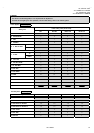
(6) User Setting
Check the user setting value of Table 2, and if setting value is different, set
the correct value.
For setting, refer to the OPERATING INSTRUCTIONS.
(7) Setting of SERVICE MENU
Verify the setting items of the SERVICE MENU, and reset where necessary.
For setting, refer to the SERVICE ADJUSTMENTS.
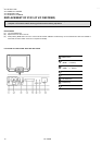
NOTE
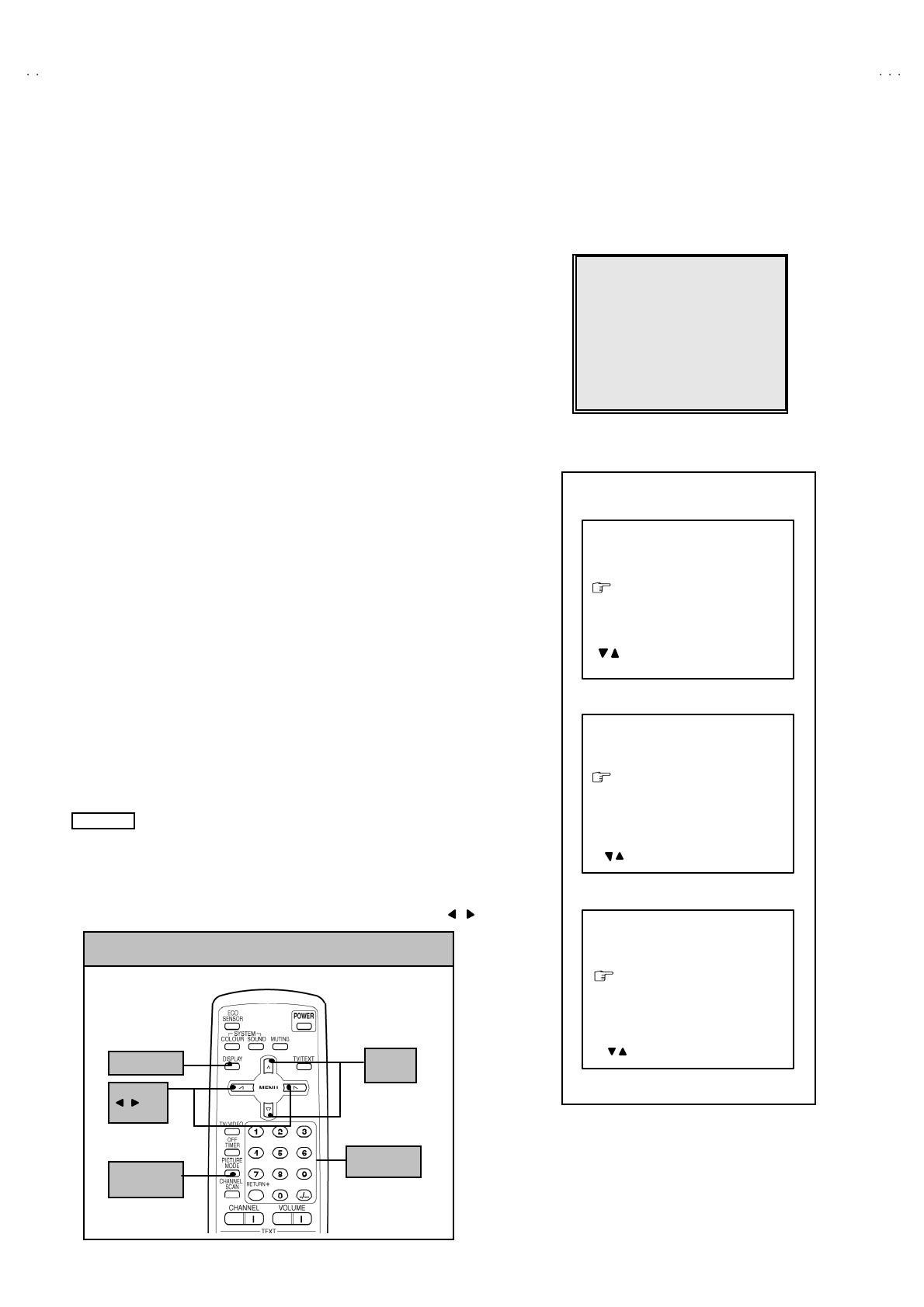
Although the key position of the RM-C90 remote control unit is different from
that of the RM-C364GY & RM-C354 remote control unit, the functions of both
units are the same So please us e the attached diagram for the RM-C90
remote control unit for the RM-C364GY & RM-C364.
By the way, MENU -/+ Key functions in the same manner as for / key.
S
ERVI
C
E MEN
U
1.IF 2.V
/C
3.DEF 4.VSM PRESET
5.PRESET
6.SETUP TOUR OFF
1-6 SELECT DISP : EXIT
******
************
***********
**********
***** **
** **
**
.
***
******
***
*** ** **
*** ** ***** ** **
*** ** **** ***
** ***** ***
** ***
Fig.1
Fig.2
DISPLAY key
MENU
/ key
MENU
▼
/
▲
key
PICTURE
MODE key
(RM-C90)
NUMBERS
key
KEY ASSIGNMENT OF REMOTE CONTROL UNIT
SYSTEM CONSTANT-Ⅰ
ⅠⅠ
Ⅰ
COL OUR :
BILINGUAL : NO
T
U
NER : M
U
ECO SENSOR : YES
LANG U AGE :
SYSTEM CONSTANT SET 1
***
***
: SELECT
- / + : OPERATE DISP : EXIT
/
SYSTEM CONSTANT-Ⅱ
ⅡⅡ
Ⅱ
B/B SOUND : OFF
LOCK : 180
COLOUR AUTO :
QSS : MINT
ALC : NO
TEXT R ATE : 2 0
SYSTEM CONSTANT SET 2
***
: SEL - / + : OPE DISP : EXIT/
SYSTEM CONSTANT-
Ⅲ
ⅢⅢ
Ⅲ
AMP TUNER : NO
VNR : YES
TEXT TABLE :
VOLUM PWM : POS
SYSTEM CONSTANT SET 3
***
: SEL - / + : OPE DISP : EXIT
/