


13
HOOKUP AND
SETTINGS
Depending on your TV and other equipment
there are various ways you can connect the
recorder. Please refer to the manuals of your
TV, VCR, Stereo System or other devices as
necessary for additional connection informa-
tion.
Notes:
• Make sure the Recorder is connected directly to the TV
and tune the TV to the correct video input channel.
• Do not connect the Recorder’s AUDIO OUTPUT jack to
the phono in jack (record deck) of your audio system.
• Do not connect the Recorder via another VCR. The
DVD image could be distorted by the copy protection
system.
• The picture and sound of a nearby TV, VCR, or radio
may be distorted during playback. Position the units
away from each other or turn off the unit after removing
the disc.
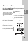
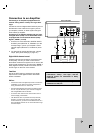
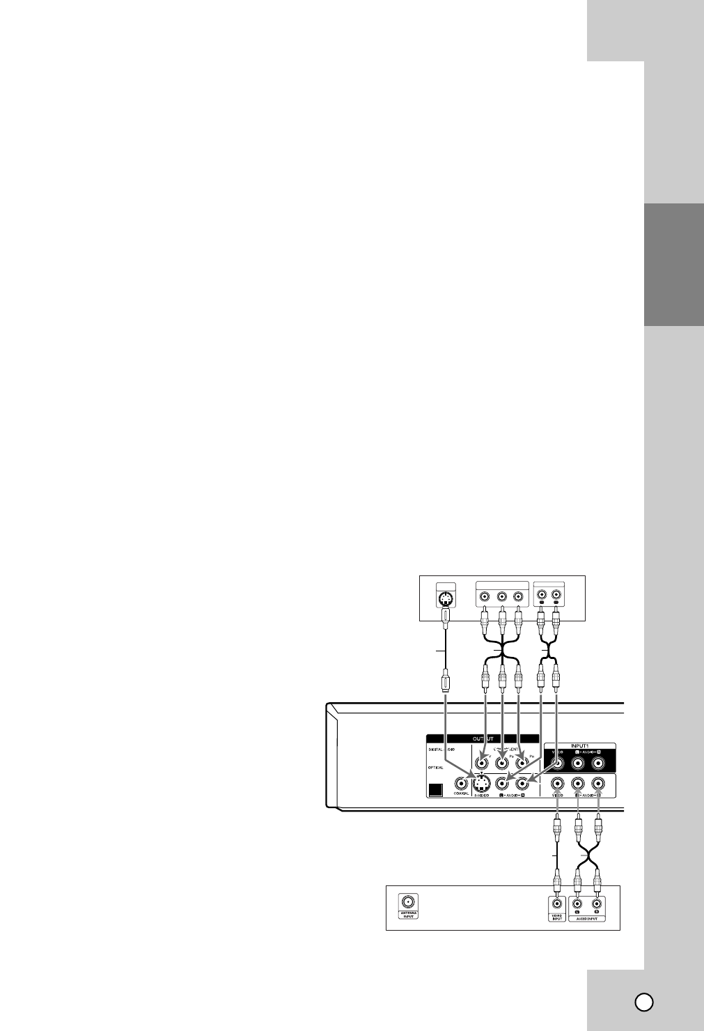
Connections to your TV
Connections to your TV
Make one of the following connections, depending on
the capabilities of your TV.
Video connection
Connect the VIDEO OUTPUT jack on the Recorder to
the video in jack on the TV using the video cable
supplied (V).
Note:
If you use this connection, set the TV’s source selector to
VIDEO.
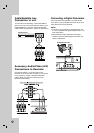
S-Video connection
Connect the S-VIDEO OUTPUT jack on the Recorder
to the S-Video in jack on the TV using the optional S-
Video cable (S).
Component Video connection
If your television is a high-definition or “digital ready”
television, you may take advantage of the Recorder’s
progressive scan output for the highest video resolu-
tion possible.
Connect the COMPONENT OUTPUT jacks on the
Recorder to the corresponding in jacks on the TV
using an optional Y P
B
PR cable (C).
Notes:
• Set the resolution to 480p using OUTPUT STATUS but-
ton on the front panel for progressive signal.
• Progressive Scan does not work with the Video or S-
Video connections.
• If your TV does not accept the Progressive Scan format,
the picture will appear scrambled.
• If the resolution is set to 720p or 1080i, the VIDEO
OUTPUT, S-VIDEO OUTPUT and COMPONENT OUT-
PUT connections are not available.
Audio connection
Connect the Left and Right AUDIO OUTPUT jacks on
the Recorder to the audio left/right in jacks on the TV
using the supplied audio cables (A1 or A2).
Rear of Recorder
A1V
Rear of TV
Rear of TV
Y
Pb
Pr
COMPONENT/PROGRESSIVE SCAN
VIDEO INPUT
L
R
AUDIO INPUT
S-VIDEO
INPUT
S
A2C
Hookup and Settings