


H EN
34
Input/Output Setting
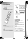
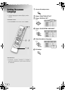
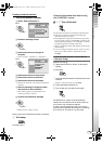
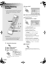
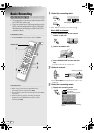
A Access the setup menu.
B Select “FUNCTION SET UP”.
C Select “VIDEO IN/OUT”.
D Set the input/output terminal.
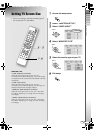
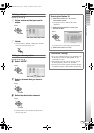
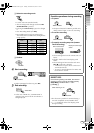
A Select and confirm on AF-1 INPUTB.
B Select and confirm on AL-1 OUTPUTB.
C Select and confirm on AL-1 INPUTB.
D Select and confirm on AL-2 SELECTB.
0 See the description below for the combinations
of settings.
E Exit setup.
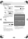
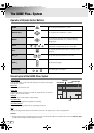
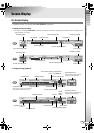
Ⅲ Possible combinations
*1 Switching to RGB signals is automatic.
*2 Component videos will be output from the [COMPONENT] terminal. Be sure to set to ACOMPONENTB if viewing via component
video.
*3 With this setting, signals from the [L-2 IN/DECODER] terminal will be output to the [L-1 IN/OUT] terminal even if this unit is
turned off, except during EPG data downloading.
*4 This setting cannot be made if AL-2 SELECTB is set to ASAT VIDEO/RGBB or ADECODERB.
*5 Will not be displayed if AČESKÁ REPUBLIKAB, AMAGYARORSZÁGB, APOLSKAB or AOTHER EASTERNB
is selected for area
setting.
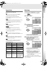
9The SCART connector supports the
connection of composite video signals.
Settings must correspond with the type of
video signal to use and the device to
connect.
.
........................................................
.
IMPORTANT:
0 For normal use, you can leave the default settings as
they are.
0 See the following page regarding each setting. Setup
Menu AF-1 INPUTB, AL-1 OUTPUTB, AL-1 INPUTB,
AL-2 SELECTB [ P102, 103] i - l
0 For image output format other than A576iB (during up
convert or progressive scan), viewing is not possible
as the images are distorted.
A, E
B - D
SELECT
FUNCTION SET UP
VIDEO IN/OUT
SELECT
CONFIRM
F-1 INPUT
VIDEO
S-VIDEO
AL-2 SELECTB (*1)
AL-1 OUTPUTB
ASCART VIDEOB ASCART S-VIDEOB ASCART RGBB ACOMPONENTB (*2)
AVIDEO/RGBB 3 3 3 3
AS-VIDEO/RGBB 3 3 3 3
ASAT VIDEO/RGBB 3 3 3 (*3)
ASAT S-VIDEO/RGBB 3 3 (*3)
ADECODERB (*5) 3 3 (*3)
AL-1 INPUTB
AVIDEOB 3 3 3 3
AS-VIDEOB 3 (*4) 3 (*4)
DR-MH300SE.book Page 34 Tuesday, November 22, 2005 5:13 PM