


9
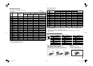
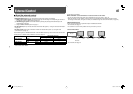
7 Available signals
The following signals are available for this monitor.
Video signals
No. Signal name
Signal format
shown in the
status display
(☞ page 7)
Input terminal
VIDEO
COMPO.
(Analog
component)*
1
E. AUDIO HD/
SD SDI
(IN 1, IN 2)*
2
DVI-D (HDCP)
(Digital component/
digital RGB)
1 NTSC NTSC
√
—— —
2PAL PA L
√
—— —
3 B/W50 B/W50
√
—— —
4 B/W60 B/W60
√
—— —
5 480/60i 480/60i —
√√ √
6 576/50i 576/50i —
√√ √
7 480/60p 480/60p —
√
—
√
8 576/50p 576/50p —
√
—
√
9 640*480/60p 640*480/60p — — —
√
10 720/60p 720/60p —
√√ √
11 720/50p 720/50p —
√√ √
12 720/30p 720/30p —
√√
—
13 720/25p 720/25p —
√√
—
14 720/24p 720/24p —
√√
—
15 1080/60i 1080/60i —
√√ √
16 1035/60i 1035/60i — √*
3
√
√*
3
17 1080/50i 1080/50i —
√√ √
18 1080/60p 1080/60p — — —
√
19 1080/50p 1080/50p — — —
√
20 1080/30p 1080/30p —
√√ √
21 1080/25p 1080/25p —
√√ √
22 1080/24p 1080/24p —
√√ √
23 1080/30psF 1080/60i — √*
3
√*
3
—
24 1080/24psF 1080/24psf —
√√
—
*
1
Analog component signals are compatible with Y on sync signals.
*
2
Compatible with EMBEDDED AUDIO signals
*
3
The signal is recognized as 1080/60i.
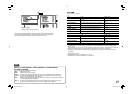
Computer signals (preset)
DVI-D (HDCP) terminals
No. Signal name
Resolution Frequency
Scan system
Horizontal Vertical Horizontal (kHz) Vertical (Hz)
1VGA60 640 480 31.5 59.9 Non-interlace
2WVGA60 852 480 31.5 59.9 Non-interlace
3SVGA60 800 600 37.9 60.3 Non-interlace
4XGA60 1024 768 48.4 60.0 Non-interlace
5WXGA (1280) 1280 768 47.8 60.0 Non-interlace
6WXGA+60
1440 900 55.9
60.0 Non-interlace
7SXGA60*
4
1280 1024 64.0 60.0 Non-interlace
8WSXGA+60*
4
1680 1050 65.2 60.0 Non-interlace
9UXGA60*
4
1600 1200 75.0 60.0 Non-interlace
10 WUXGA60*
4
1920 1200 74.0 60.0 Non-interlace
11 720/60p 1280 720 45.0 60.0 Non-interlace
12 1080/60p*
4
1920 1080 67.5 60.0 Non-interlace
13 720/50p 1280 720 37.5 50.0 Non-interlace
14 1080/50p*
4
1920 1080 56.25 50.0 Non-interlace
*
4
When No. 7–10, 12 and 14 signals come in, thin lines will become obscured because their signal resolution is higher
than the screen resolution.
• Non-preset signals may not be displayed normally even if their frequency is within the acceptable range (☞
“Horizontal/vertical frequency (computer signal)” on page 21).
• When a preset signal comes in, the signal format is shown on the status display. For other signals, the
resolution is shown.
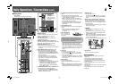
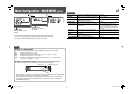
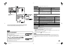
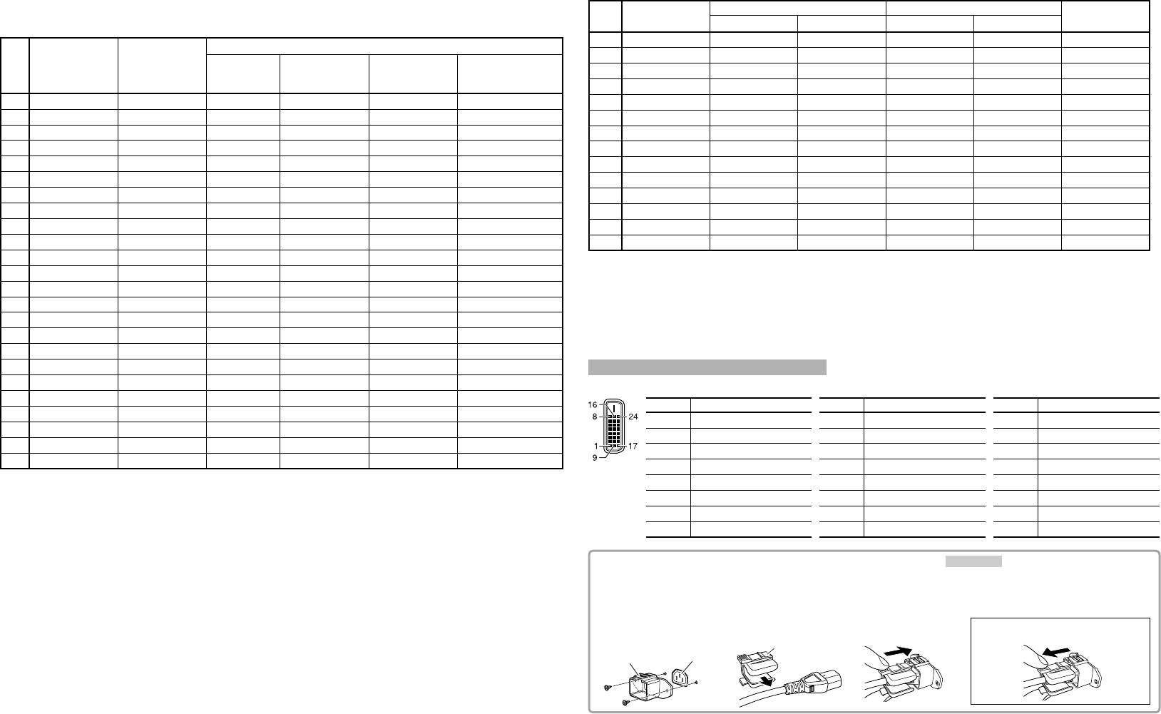
Specification of the DVI-D (HDCP) terminal
Connect it to the DVI-D output terminal on a personal computer.
Pin No. Input signal Pin No. Input signal Pin No. Input signal
1
T.M.D.S Data 2–
9
T.M.D.S Data 1–
17
T.M.D.S Data 0–
2
T.M.D.S Data 2+
10
T.M.D.S Data 1+
18
T.M.D.S Data 0+
3
T.M.D.S Data 2 shield
11
T.M.D.S Data 1 shield
19
T.M.D.S Data 0 shield
4
NC
12
NC
20
NC
5
NC
13
NC
21
NC
6
DDC Clock
14
+5 V Power
22
T.M.D.S Clock shield
7
DDC Data
15
GND
23
T.M.D.S Clock+
8
NC
16
Hot Plug Detect
24
T.M.D.S Clock–
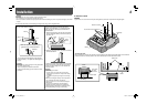
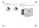
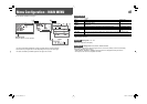
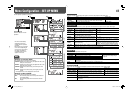
AC IN
terminal
Case
Cover
To detach the cover
23
1
CAUTION
• Use only the provided screws.
• Make sure the plug will not be pulled out
after the cover is attached to the case.
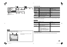
Attaching the power cord holder
The provided power cord holder prevents accidental
disconnection of the AC power cord from the AC IN terminal.
• The power cord holder consists of two parts, a case and a
cover.
√: Acceptable
—: Not acceptable
DT-V17L3D_EN3.indd 9DT-V17L3D_EN3.indd 9 08.6.25 10:29:04 PM08.6.25 10:29:04 PM