


INPUT 4
S VIDEOVIDEO
INPUT 1
R
L MONO
AUDIO
OVER
R
L MONO
R
L
75Ω
(VHF / UHF)
AUDIO
COMPONENT
VIDEO
COMPONENT
VIDEO
Y
P
B
P
R
AV COMPULINK
AUDIO OUT
INPUT 2
WALL
CABLE or ANTENNA
OUT
OR
OR
TWO-WAY
SPLITTER
IN
OUT OUT
CABLE BOX
OUT IN
VCR
IN
OUT
VLR
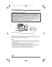
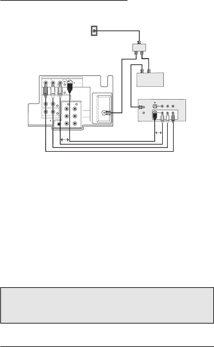
Illustration of AV-27F803
Connections
15
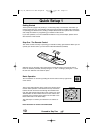
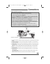
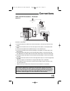
The connection diagrams are intended to show some basic general connections.
Some cable companies may require special connections to properly use your televi-
sion or 2-tuner PIP function. If you follow these diagrams and either the television or
PIP does not work properly, contact your local cable operator for more connection
information. Please see page 47 for more information on the PIP feature.
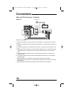
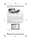
Cable and VCR Connections - Continued
1) Connect the antenna or cable TV wire from the wall outlet, in to the RF Input of the two-way
splitter.
2) Connect an RF cable from the one of the RF Outputs on the splitter, in to the cable box RF
Input.
3) Connect an RF cable from the Cable Box Output, in to the VCR RF Input.
4) Connect an RF cable from the other the RF Output on the splitter, in to the RF Input on the
back of the TV.
5) Connect the yellow video cable out from the VCR’s Video Output, in to the TV’s Video Input
jack, OR connect an S-Video cable from the VCR’s S-Video output, to the TV’s S-Video input.
6) Connect the white audio cable out from the VCR’s Left Audio Output, in to the TV’s Left Audio
Input jack.
7) Connect the red audio cable out from the VCR’s Right Audio Output, in to the TV’s Right Audio
Input jack.
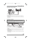
• Please see page 47 for information on using the PIP feature with a Cable Box.
• If your VCR is a mono sound unit, it will have only one Audio Out jack. Connect it to the
TV’s Left Audio Input.
• Please consult your VCR’s owner’s manual for more information on its operation.
Diagram #3
AV-27,32,36F703/713/803 English 6/14/02 5:07 PM Page 15