


Connections
13
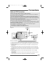
The connection diagrams are intended to show some basic general connections.Some
cable companies may require special connections to properly use your television or
2-tuner PIP function.If you follow these diagrams and either the television or PIP does not
work properly, contact your local cable operator for more connection information. Please
see page 44 for more information on the PIP feature.
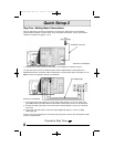
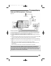
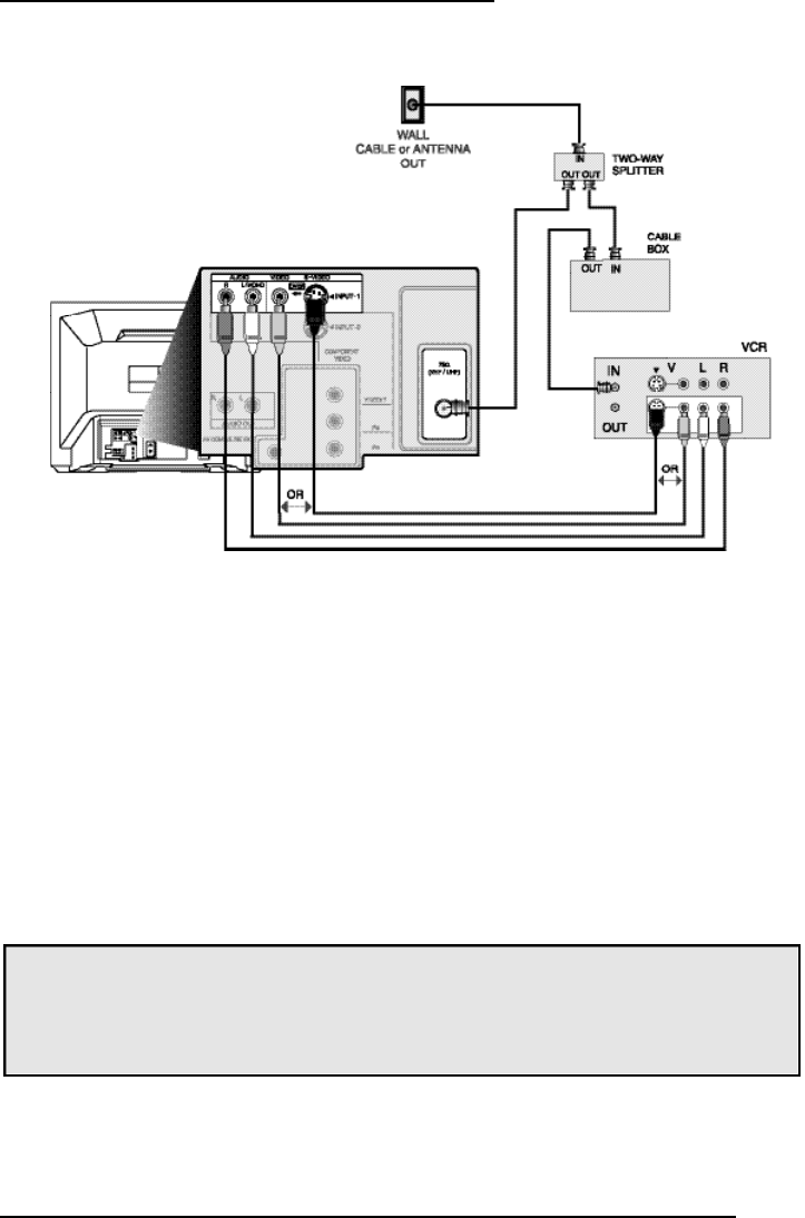
Cable and VCR Connections - Continued
1) Connect the antenna or cable TV wire from the wall outlet, in to the RFInput of the two-way splitter.
2) Connect an RFcable from the one of the RFOutputs on the splitter, in to the cable box RF I n p u t .
3) Connect an RFcable from the Cable Box Output, in to the VCR R FI n p u t .
4) Connect an RFcable from the other the RFOutput on the splitter, in to the RFInput on the back of
the T V.
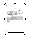
5) Connect the yellow video cable out from the VCR’s Video Output, in to the T V ’s Video Input jack, O R
connect an S-Video cable from the VCR’s S-Video output, to the T V ’s S-Video input.
6) Connect the white audio cable out from the VCR’s Left Audio Output, in to the T V ’s Left Audio Input
j a c k .
7) Connect the red audio cable out from the VCR’s RightAudio Output, in to the T V ’s Right Audio Input
j a c k .
• Please see page 44 for information on using the PIP feature with a Cable Box.
• If your VCR is a mono sound unit, it will have only one Audio Out jack. Connect it to the TV’s
Left Audio Input.
• Please consult your VCR’s owner’s manual for more information on its operation.
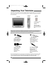
Illustration of AV-32D502
Diagram #3
D502/302/202 mini-IB 4/5/01 9:40 AM Page 13