


A2
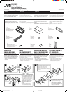
5
1
3
2
15
B1 B3 B5 B7
B2 B4 B6 B8
A5 A7
A2 A4
A8
A8
A7
A5
A4
B5B6
B4
B3
B8 B7
B2 B1
*
1
*
1
1
2
3
4
6
B1 B3 B5 B7
B2 B4 B6 B8
A5 A7
A2 A4
A8
3
*
2
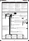
Before checking the operation of this unit prior to
installation, this lead must be connected, otherwise power
cannot be turned on.
*
2
Vor der Überprüfung der Funktionsfähigkeit des Geräts
vor dem Einbau, muß diese Leitung angeschlossen
werden, da sonst die Stromversorgung nicht
eingeschaltet werden kann.
*
2
Pour vérifier le fonctionnement de cet appareil avant
installation, ce fil doit être raccordé, sinon l’appareil ne
peut pas être mis sous tension.
*
2
Voordat u controleert of het apparaat werkt (alvorens het te
installeren), moet deze draad aangesloten zijn. Als dit niet het
geval is, kan de stroom niet worden ingeschakeld.
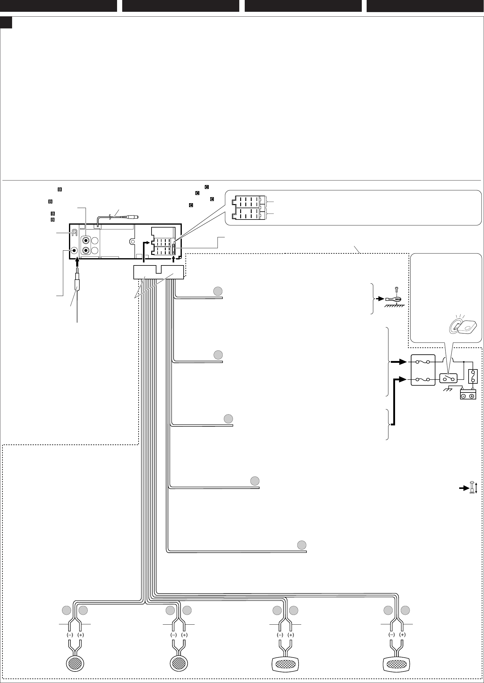
15 A fuse
15 A Sicherung
Fusible 15 A
Zekering 15 A
Yellow*
2
Gelb*
2
Jaune
*
2
Geel *
2
Blue with white stripe
Blau mit weißem Streifen
Bleu avec bande blanche
Blauw met witte streep
Red
Rot
Rouge
Rood
To cellular phone system
Zur Mobiltelefon
À un système de téléphone cellulaire
Naar het mobiele-telefoonsysteem
Fuse block
Sicherungsblock
Porte-fusible
Zekeringblok
To a live terminal in the fuse block connecting to the car battery
(bypassing the ignition switch) (constant 12 V)
Zur einer stromführenden Anschlußklemme im Sicherungsblock zum
Anschließen an die Autobatterie (Umgehen des Zündschalters)
(konstant 12 V)
À une borne sous tension du porte-fusible connectée à la batterie de
la voiture (en dérivant l’interrupteur d’allumage) (12 V constant)
Naar een onder spanning staande aansluitklem in het zekeringblok die is
aangesloten op de accu van de auto (u passeert de ontstekingsschakelaar)
(constant 12 V)
To metallic body or chassis of the car
Zur metallenen Karosserie oder zum Fahrwerk des Autos
Vers corps métallique ou châssis de la voiture
Naar metalen ondergrond of chassis van de auto
*
1
Not included for this unit
*
1
Wird nicht mit Gerät mitgeliefert
*
1
Non fourni avec cet appareil
*
1
Niet bij het apparaat inbegrepen
Black
Schwarz
Noir
Zwart
To an accessory terminal in the fuse block
Zur einer Zubehöranschlußklemme im Sicherungsblock
Vers borne accessoire du porte-fusible
Naar een aansluitklem in het zekeringblok
Gray with black stripe
Grau mit schwarzem
Streifen
Gris avec bande noire
Grijs met zwarte streep
White
Weiß
Blanc
Wit
White with black stripe
Weiß mit schwarzem
Streifen
Blanc avec bande noire
Wit met zwarte streep
Green with black stripe
Grün mit schwarzem
Streifen
Vert avec bande noire
Groen met zwarte streep
Gray
Grau
Gris
Grijs
Green
Grün
Vert
Groen
Purple with black stripe
Lila mit schwarzem
Streifen
Violet avec bande noire
Paars met zwarte streep
Purple
Lila
Violet
Paars
Rear ground terminal
Hintere Erdungscan–
schlußklemme
Borne arrière de masse
Massaklem aan de achterkant
To the remote lead of other equipment or power aerial if any (200 mA max.)
Zum Zusatzkabel des anderen Geräts oder der Motorantenne, sofern vorhanden
(max. 200 mA)
Au fil de télécommande de l’autre appareil ou à l’antenne automatique s’il y en a une
(200 mA max.)
Naar afstandsdraad van andere apparatuur of antenne met circuit indien aanwezig (200 mA max.)
Vor dem Anschließen: Die Verdrahtung im
Fahrzeug sorgfältig überprüfen. Falsche
Anschlüsse können ernsthafte Schäden am
Gerät hervorrufen.
Die Leiter des Stromkabels und die Leiter des
Anschlusses im Fahrzeug können sich farblich
unterscheiden.
1
Die farbigen Adern des Stromkabels in der
Reihenfolge anschließen, wie in der
Abbildung unten gezeigt.
2
Das Antennenkabel anschließen.
3
Die Kabelbäume am Gerät anschließen.
Hinweis: Verfügt Ihr Fahrzeug nicht über eine
Zubehöranschlußklemme, die Sicherung von
der 1. Sicherungsposition (Erstposition) in die 2.
Sicherungsposition versetzen, die rote Leitung
(A7) an der (+) Batterieanschlußklemme
anschließen.
• Die gelbe Leitung (A4) wird in diesem Fall
nicht verwendet.
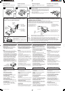
Before connecting: Check the wiring in the
vehicle carefully. Incorrect connection may
cause serious damage to this unit.
The leads of the power cord and those of the
connector from the car body may be different in
color.
1
Connect the colored leads of the power cord
in the order specified in the illustration
below.
2
Connect the aerial cord.
3
Finally connect the wiring harness to the unit.
Note: If your vehicle does not have any
accessory terminal, move the fuse from the
fuse position 1 (initial position) to fuse position
2, and connect the red lead (A7) to the positive
(+) battery terminal.
• The yellow lead (A4) is not used in this case.
Avant de commencer la connexion:
Vérifiez
attentivement le câblage du véhicule. Une
connexion incorrecte peut endommager
sérieusement l’appareil.
Le fil du cordon d’alimentation et ceux des
connecteurs du châssis de la voiture peuvent
être différents en couleur.
1 Connectez les fils colorés du cordon
d’alimentation dans l’ordre spécifié sur
l’illustration ci-dessous.
2 Connectez le cordon d’antenne.
3 Finalement, connectez le faisceau de fils à
l’appareil.
Remarque:
Si votre véhicule ne possède pas de
borne accessoire, déplacez le fusible de la
position de fusible 1 (position originale) à la
position de fusible 2 et connectez le fil rouge
(A7) à la borne positive (+) de la batterie.
•
Le fil jaune (A4) n’est pas utilisé dans ce cas.
Alvorens de verbindingen tot stand te
brengen: Moet u de bedrading in de auto
zorgvuldig. Het apparaat kan door verkeerde
verbindingen ernstige schade oplopen.
De draden van het stroomsnoer verschillen mogelijk
van kleur metde aansluitingen op het chassis van de
auto.
1
Verbind de gekleurde draden van het
stroomsnoer in de afbeelding hieronder
aangegeven volgorde.
2
Sluit de antenne aan.
3
Verbind de draadbundel daarna met het apparaat.
Opmerking: Als uw voertuig niet beschikt over
een aansluitklem, moet u de zekering verplaatsen
van stand 1 (beginstand) naar stand 2 en moet u de
rode draad (A7) met de pluspool (+) van de accu
verbinden.
• In dit geval wordt de gele draad (A4) niet gebruikt.
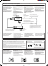
Line out (see diagram )
Schutz kappen Signalausgang
(siehe Schaltplan )
Sortie de ligne
(voir le diagramme )
Uitgang (zie schema )
A
Left speaker (rear)
Linker Lautsprecher (hinten)
Enceinte gauche (arrière)
Linkerspeaker (achterin)
Right speaker (front)
Rechter Lautsprecher (vorne)
Enceinte droit (avant)
Rechterspeaker (voorin)
Left speaker (front)
Linker Lautsprecher (vorne)
Enceinte gauche (avant)
Linkerspeaker (voorin)
Right speaker (rear)
Rechter Lautsprecher (hinten)
Enceinte droit (arrière)
Rechterspeaker (achterin)
D
Brown
Braun
Marron
Bruin
Ignition switch
Zündschalter
Interrupteur d’allumage
Ontstekingsschakelaar
Typical Connections / Typische Anschlüsse / Raccordements typiques / Normale verbindingen
Aerial terminal
Antennenanschlußklemme
Borne de l’antenne
Aansluitpunt antenne
Fuse position 2 / 2. Sicherungsposition /
Position de fusible 2
/ Zekering, stand 2
Fuse position 1 / 1. Sicherungsposition /
Position de fusible 1
/
Zekering, stand 1
To steering wheel remote controller (see diagram )
An Lenkradfernbedienung (siehe Schaltplan )
Pour la télécommande de volant (voir le diagramme )
Naar stuurwiel-afstandsbediening (zie schema )
NEDERLANDS
FRANÇAIS
DEUTSCHENGLISH
Instal3-4_KD-G401_005A_f.p65 17/11/03, 3:35 PM3