


14
Preparations and Main Functions
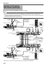
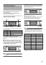
Intercommunications between operators are necessary in a
system composed of multiple cameras and remote control
units.
Ⅵ
The factory settings vary depending on the model.
RM-HP790DU : RTS system. *
1
RM-HP790DE : 2-wire system, which uses the [H] and [C]
terminals. *
1
*1 If tally and intercom settings (for changing model from DU to DE
or vice versa) are required, the setting of the internal circuitry
should be changed; consult the nearest JVC-authorized service
agent. (The modifications and adjustments will be carried out
with charge.)
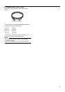
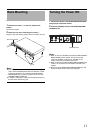
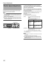
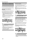
An intercom connector
An intercom connector is provided on the front panel of the
RM-HP790DU/RM-HP790DE
.
The volume level of the headset’s earphone can be adjusted
using the [INTERCOM LEVEL] control.
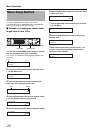
Intercom Input Connector (XLR 5 Pin)
Input connector for intercom headset. (Dynamic only)
Recommended headset: DT109 (Beyerdynamic)
Memo :
● Examples of suitable headsets
DT109 (Beyerdynamic)
Headsets from other manufacturers with:
Microphone output impedance: 50 K to 200 K
Earphone input impedance: 50 K to 400 K
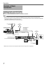
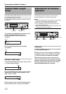
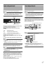
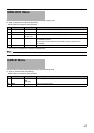
This function makes it possible to call the camera operator
without using the intercom. The camera operator is informed
of the call by the blinking of the tally lamp on the camera.
When the [CALL] button is pressed, the button light is lit and
the tally lamp on the camera blinks. Pressing the button
again turns off both the button light and the blinking of the
camera’s tally lamp.
Memo :
● The tally lamp on the camera does not blink or light when
either the camera or the RM-HP790DU/RM-HP790DE are
switched off. When the [CALL] button of the camera is
pressed, the [CALL] button of RM-HP790DU/RM-
HP790DE blinks in red.
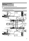
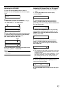
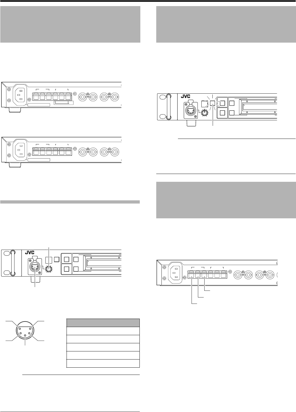
The [TALLY] lamp on the front panel lights when signals are
applied to the [TALLY] terminals on the rear panel.
Ⅵ
The factory settings vary depending on the model.
RM-HP790DU : Contact supply mode*
1
RM-HP790DE : Voltage supply mode*
1
● [TALLY] lamp will light up in red when [PGM] (Program)
terminal and [C] (Common) terminal are in the contact
status (RM-HP790DU) or when 2 points of rated voltage
are ignited (RM-HP790DE).
● [TALLY] lamp will light up in green when [PVW] (Preview)
terminal and [C] (Common) terminal are in the contact
status (RM-HP790DU) or when 2 points of rated voltage
are ignited (RM-HP790DE).
*1 If tally and intercom settings (for changing model from DU to DE
or vice versa) are required, the setting of the internal circuitry
should be changed; consult the nearest JVC-authorized service
agent.
(The modifications and adjustments will be carried out with
charge.)
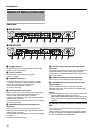
Intercom
AC ` IN AC120V 60Hz
TALLY
PGM PVW C
INTERCOM
AUX VIDEO INPUT GENLOCK INPUT
H
RTS
CG
AC ` IN 230V` 50Hz
TALLY
PGM PVW C
INTERCOM
AUX VIDEO INPUT GENLOCK INPUT
HCG
CALLTALLY
INTERCOM
LEVEL
FULL AUTO F1
SHUTTER
GAIN
F2
BARS
2. CABLE
[INTERCOM LEVEL] control
Intercom connector
A
B
C
D
E
Signal
A MIC (H)
B MIC (C)
C EAR (C)
D EAR (H) - LEFT
E EAR (H) - RIGHT
(Surface profile)
Camera Operator Call
Tally
CALLTA LLY
INTERCOM
LEVEL
FULL AUTO F1
SHUTTER
GAIN
F2
BARS
2. CABLE
[CALL] Button
TALLY
PGM PVW C
INTERCOM
AUX VIDEO INPUT GENLOCK INPUT
HCG
[C] (Common) terminal
[PVW] (Preview) terminal
[PGM] (Program) terminal