


42
PD-Z42DV4/PD-Z35DV4 / LCT1665-001A / English
ENGLISH
Additional preparation
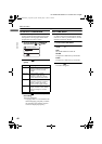
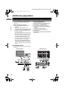
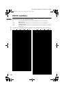
Connecting external equipment
Connect the equipment to the TV, making
the correct rear panel and front panel
connections.
Before connecting anything:
• Read the manuals that came with the
equipment.
Depending on the equipment, the
connection method may be different from
the diagram. Also, the equipment settings
may need to change depending on the
connection method.
• Turn off all the equipment including the TV.
• The “Specifications” on page 49 give the
details of the VIDEO terminals. If you are
connecting equipment not listed in the
following connection diagram, see the
table to choose the best VIDEO terminal.
• Connecting cables are not supplied.
• If the VCR’s audio output is in mono,
connect the VCR’s AUDIO OUT (audio
output) terminal and the TV’s VIDEO-4
AUDIO L/MONO terminal with an audio
cable.
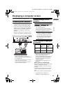
Connecting the PC
For details, see “Connecting to the computer”
on page 41.
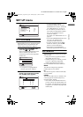
1 VCR (composite signal)
2 VCR (S-VIDEO signal; Y/C)
3 VCR for recording (composite signal)
4 DVD player (composite signal)
5 DVD player (S-VIDEO signal; Y/C)
6 DVD player (component video signals;
Y/Pb/Pr)
7 TV game (composite signal)
8 TV game (S-VIDEO signal; Y/C)
9 Headphones
0 Camcorder (composite signal/S-VIDEO
signal; Y/C)
R
VIDEOLR
CENTER CHANNEL
INPUT
AUDIO
VIDEOL/MNORAUDIO
LRAUDIO VIDEO
VIDEO-1
VIDEOLRAUDIO
OUT
IN
VIDEO-2
IN
VIDEO-3
IN
AUDIO
OUT
SUB WOOFER
OUT
L
YCb/Pb
COMPONENT
Cr/Pr
YCb/Pb
COMPONENT
Cr/Pr
S-VIDEO
S-VIDEO
CH
A
NN
EL
ME
N
U
/O
K
T
V
/V
I
D
EO
L/MONO-AUDIO-RVIDEOS-VIDEO
CHANNEL
VOLUME
MENU/OK TV/VIDEO
PC IN(D-SUB)
VIDEO-4
Back of the TVFront of the TV
Body_Eng.fm Page 42 Monday, May 17, 2004 1:31 PM