


7
8
SECTION 2 – BASIC OPERATION
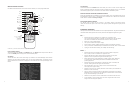
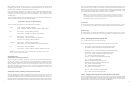
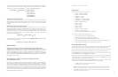
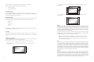
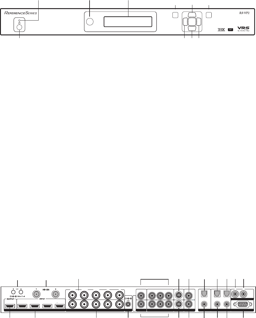
Front Panel Overview
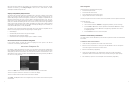
Status LED – This displays the current state of the RS-VP2
Off = The unit is in standby mode
Red = No signal detected
Blue = The unit is processing the signal
Blinking Blue = There is a problem with HDCP authentication
Green = The unit detects an unsupported signal
Blinking Green = In Pass Through there is a problem with HDCP authentication
On/Standby Button – This toggles unit power between On and Standby.
IR Window – This is where all IR commands are received by the RS-VP2. Do not obstruct this win-
dow.
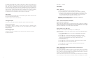
Front Panel Display (FPD) – This is where all information from the on screen display (OSD) is
duplicated to assist in the setup of your RS-VP2.
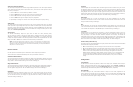
NOTE: When navigating the Menu, the Front Panel Display (FPD) always shows the current selec-
tion on the bottom line and the menu/submenu item on the top line. When you change a value of a
setting, the value is on the bottom line and the title of the parameter is on the top line.
Navigation Buttons – These buttons are available both on the front panel and on the remote control.
NOTE: Switching Inputs using the Navigation buttons – You can switch inputs on the front panel of
the RS-VP2 or using the remote using the navigation buttons. To do this, press the ▼ or ▲ without
pressing the Menu button rst.
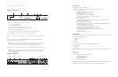
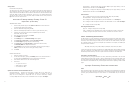
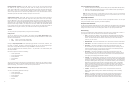
Back Panel Overview
Video Inputs
The RS-VP2 has eleven (11) video inputs.
The formats, colorspace and bit-depth that the inputs support are as follows:
• Video 1 and Video 2
— Formats: NTSC, PAL, PAL-M and SECAM
• S-Video 1 and S-Video 2
— Formats: NTSC, PAL, PAL-M and SECAM
• Component/RGBS 1 and Component/RGBS 2
— Formats: 480i/p-60, 576i/p-50, 720p-50/60, 1080i-50/60
— Colorspace: YPbPr and RGBS
• RGBHV/Component
— Formats: 480p-60, 576p-50, 720p-50/60, 1080i-50/60, VGA/SVGA/XGA/SXGA-60
— Colorspace: RGBHV and YPbPr
• HDMI 1, HDMI 2, HDMI 3 and HDMI 4
— Formats: 480i/p-60, 576i/p-50, 720p-50/60, 1080i-50/60, 1080p-24/25/30/50/60,
VGA-60, SVGA-60, XGA-60, SXGA-60
— Colorspace RGB/YCbCr 4:4:4/YCbCr 4:2:2
— Bit-Depth: 8/10-bit processed Up to 12-bit passthrough
• Optional Precision HD-SDI Dual Input Module
— Formats: 480i-60, 576i-50, 720p-60, 1080i-50/60, 1080p-24/25/30
— Colorspace: YCbCr 4:2:2
— Bit-Depth: 8/10-bit processed
Video Outputs
The RS-VP2 has two video outputs, one analog and one digital. The analog output on the RS-VP2
can output the following signal types:
• YPbPr (Component)
• RGBHV
• RGsB
• RGBS
The HDMI digital video output can output the following signal types:
• RGB 4:4:4
• YCbCr 4:2:2
• YCbCr 4:4:4
To connect the RS-VP2 to a display that has a DVI input, use either an HDMI-to-DVI cable or an
adapter.
Audio Inputs
There are nine (9) audio inputs on the RS-VP2:
• Two (2) Optical Digital inputs
• Two (2) Coaxial Digital inputs
• One (1) Analog (L/R) input
• Four (4) HDMI 1.3 inputs
While the digital and analog audio inputs can be assigned to any one of the video inputs, the HDMI
audio inputs are tied directly to the HDMI video signal connected on the same input.
t ,p,q,u
MENU
EXIT
HDMI
1234
INPUT
OUTPUT
1
3
2
4
SERIAL PORT
ANALOG AUDIO INPUT
Y (G) Pb (B) Pr (R) HV
DC In
Y (G) Pb (B) Pr (R)
1
2
1
2
1
2
1
2
LR
ANALOG VIDEO
I
N
P
U
T
S
I
N
P
U
T
O
U
T
P
U
T
Front Panel Display (FPD)
Navigation Keys
Up
On/Standby Left Down Right
Menu Exit
Power
Video 1
Video 2
Optical
Digital
Output
Coaxial
Digital
Output
Optical
Digital Input
1 & 2
Coaxial
Digital Input
3 & 4
Serial Port
S-Video 1
S-Video 2Component/RGBS 2
Component/RGBS 1
RGBHV/Component
Output
HDMI Inputs
1–4
HDMI Output
Analog Audio
Input
DIGITAL AUDIOS-VIDEOVIDEOSYNCPOWER
HD-SDI Inputs (Optional)
1 & 2
RGBHV/Component
Input
IR WindowStatus LED Enter
COMPONENT
12V Triggers
1 & 2
MENU
EXIT
Front Panel Display (FPD)
Adjustment Buttons
Up
On/Standby Left Down Right
Menu
Exit
IR Window
Status LED