


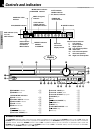

12
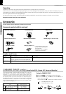
Preparations
DVR-505/DVR-7000 (EN)
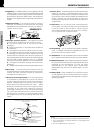
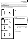
System Connections
Caution:
Do not plug in the power lead until all connec-
tions are completed.
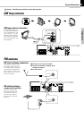
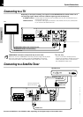
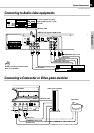
Make connections as shown below.
When connecting the related system components, refer also
to the instruction manuals of the related components.
Caution
Be sure to adhere followings. Or proper ventilation will be blocked causing damage or
fire hazard.
÷ Do not place any objects impairing heat radiation onto the top of unit.
÷ Leave a space around the unit (from the largest outside dimension including pro-
jection) equal or greater than, shown below.
Top panel : 50 cm Side panel : 10 cm Back panel : 10 cm
Malfunction of microcomputer
If operation is not possible or erroneous
display appears even though all connec-
tions have been made properly, reset the
microcomputer referring to “In case of
difficulty”. „
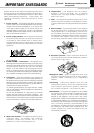
Caution : Read this page carefully to ensure
safe operation.
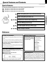
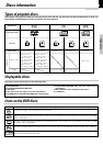
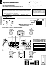
Loudspeakers
–
+
12
Speaker
Front right
Center
Front left
Surround right
Subwoofer
Surround left
Color of the speaker terminal
panel on the main unit
Red
Green
Blue
Orange
Brown
Gray
Front
speaker
R
Subwoofer
Surround
speaker
R
White
tube
Black tube
Color tube
Speaker terminal
Upper side mark
Front
speaker
L
Surround
speaker
L
Center speaker
Excessive insertion of the cable can
cause defective contact.
Note
Note
The figure shows an example for the speakers for DVR-505.
Connect the speaker cable terminals
to the terminals with the same color
at the speaker terminal panel on the
main unit. Connect matching the
color of the speaker terminal (+ side)
and the color of the speaker cable
tube.
Speakers for DVR-7000