EXTERNAL EQUIPMENT SETUP
33
VCR SETUP
Antenna Connection
■
To avoid picture noise
(
interference
)
, leave an adequate distance between the VCR and TV.
■
Use the ISM feature in the Option menu to avoid having a fixed image remain on the screen for a long period
of time
(
Plasma TV models
only)
. If the 4:3 picture format is used; the fixed images on the sides of the screen
may remain visible on the screen. This phenomenon is common to all TVs and is not covered by warranty.
ANTENNA/
CABLE IN
E)
COAXIAL
UDIO OUT
AUDIO OUT
AV IN 1
EO L R
(MONO)
AUDIO
L R
S-VIDEO VIDEO
OUTPUT
SWITCH
ANT IN
ANT OUT
Wall Jack
Antenna
1
2
REMOTE
CONTROL IN
RS-232C IN
(SERVICE ONLY)
OPTIC
COAX
ANTENNA/
CABLE IN
COMP
AUDIO
L R
S-VIDEO VIDEO
OUTPUT
SWITCH
ANT IN
ANT OUT
R
Wall Jack
Antenna
1
2
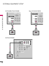
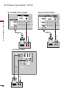
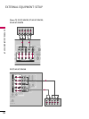
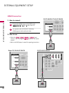
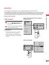
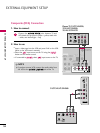
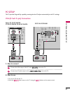
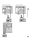
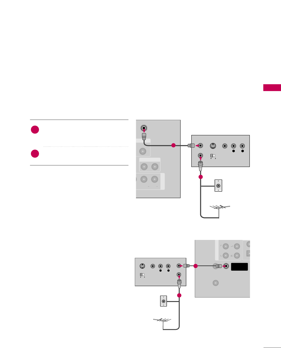
Connect the RF antenna out socket of the
VCR to the
AANNTTEENNNNAA//CCAABBLLEE IINN
sock-
et on the TV.
Connect the antenna cable to the RF
antenna in socket of the VCR.
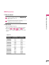
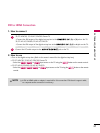
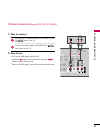
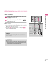
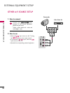
1. How to connect
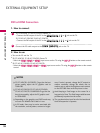
2. How to use
■
Set VCR output switch to 3 or 4 and then
tune TV to the same channel number.
■
Insert a video tape into the VCR and press
PLAY on the VCR.
(
Refer to the VCR owner’s
manual.
)
2
1
Plasma TV, 32/37/42LG30, 37/42/47/52LG50,
32/42/47/52LG70
32/37/42/47/52LG60


