


- 9 -
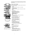
¡ Safety Precautions
1. It is safe to adjust after using insulating transformer between
the power supply line and chassis input to prevent the risk of
electric shock and protect the instrument.
2. Never disconnect leads while the TV receiver is on.
3. Don't short any portion of circuits while power is on.
4. The adjustment must be done by the correct appliances.
5. Unless otherwise noted, set the line voltage to 230Vac¡
10%, 50Hz.
5. The adjustment of TVshould be performed after warming up
for 15 minutes.
¡ Test Equipment required
1. RF signal generator (with pattern generator)
2. DC Power Supply
3. Multimeter (volt meter)
4. Oscilloscope
5. Color analyzer
¡
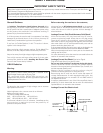
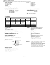
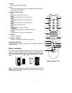
PIF (Picture Intermediate Frequency) Adjustment
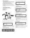
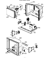
1) Connect the measuring equipment to the Main Board as
shown in Fig.1.
2) Set RF frequency and output level of RF SIGNAL
GENERATOR as shown Table 1.
3) Turn off S1 and S3 and on S2.
4) Adjust L104 so that the DC voltage may be 2.4¡ 0.05Vdc.
(Table 1)
¡ LÕ VCO Adjustment (For SECAM-LÕ MODEL)
1) Connect the measuring equipment to the Main Board as
shown in Fig.1.
2) Set RF frequency and output level of RF SIGNAL
GENERATOR as shown Table 1.
3) Turn on S1,S3 and off S2.
2) Adjust VR122 so that the DC Voltage may be 2.4¡ 0.05Vdc.
¡
RF AGC (Automatic Gain Control) Adjustment
1) Input PAL-B/G 05 CH.
2) Connect Multimeter to TP2(J15),AGC adjustment point.
3) Adjust VR121 until the voltage of Multimeter becomes
2.5¡ 0.1V.
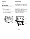
¡ Screen Voltage Adjustment
1) Tune the RF Modulator to receive a PAL or SECAM signal.
2) Press MIX button on remote controller for Service to get into
the Screen Adjust Mode.
3) Adhere the Color Analyzer on the White window of CPT
face.
4) Adjust Screen Volume of FBT so that the luminance of White
window is 12¡ 1 FL.
¡ Focus Adjustment
1) Tune the TV set to receive a digital pattern.
2) Adjust the upper Focus volume of FBT for the best focus of
vertical line B.
3) Adjust the lower Focus volume of FBT for the best focus of
area A.
4) Repeat above step 2) and 3) for the best overall focus.
IC101
TDA4470
TP1(VCO)
IC102(KI7805)
22
7
13
14
1
0.01uF
JP1
L104
9V
Power-
Supply
V Multimeter or Oscilloscope
JP2
38.9MHz
34.25MHz
(B/G,D/K,I,L)
(SECAM-L')
100 ohm
S1
5V
4.7 Kohm
S3
S2
JP3
100 ohm
Q122
VR122
R108
R144
Test Point : TP1
Adjust : L104
Test Point : TP1
Adjust : VR122
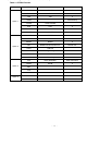
Frequency
38.9MHz
34.25MHz
System
B/G,D/K/I,SECAM-L
SECAM-LÕ
Modulation
OFF
OFF
Output level
10mVp-p
10mVp-p
Adjust
L104
VR122
Fig. 1 : Connection Diagram of Equipment for PIF Adjustment
ADJUSTMENT INSTRUCTIONS
Test Point : TP 2(J15)
Adjust : VR121
Test Point : CPT Face
Adjust : Screen Control of FBT
Test Point : Observing Display
Adjust : Focus control of FBT