


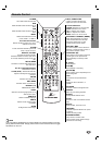
PREPARATION
11
Connections
ips
Depending on your TV and other equipment you wish to
connect, there are various ways you could connect the
DVD+VCR. Use connections described on pages 11-13.
Please refer to the manuals of your TV, VCR, Stereo
System or other devices as necessary to make the best
connections.
For better sound reproduction, connect the DVD+VCR’s
DVD/VCR AUDIO OUT jack to the audio in jacks of your
amplifier, receiver, stereo or audio/video equipment. See
Optional, Preferred TV Connections on pages 12-13.
Caution
Make sure the DVD+VCR is connected directly to the TV.
Tune the TV to the correct video input channel.
Do not connect the DVD+VCR’s DVD/VCR AUDIO OUT
jack to the phono in jack (record deck) of your audio
system.
Do not connect your DVD+VCR via your VCR. The DVD
image could be distorted by the copy protection system.
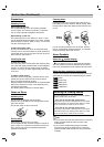
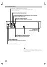
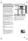
Connecting Antenna/Cable TV to
DVD+VCR
11
Disconnect the antenna leads from the rear of the
TV.
22
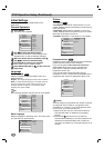
Identify the type of cable from your antenna. If it is
a round cable as illustrated, it is a 75 ohm coaxial
antenna cable. This cable will connect directly to
the jack marked ANT.IN on your DVD+VCR.
ip
If your antenna lead wire is a flat type antenna cable,
connect it to an Antenna Adapter (300-ohm to 75-ohm)
(not supplied) and slip the Adapter onto the ANT.IN
jack. The Adapter does not screw on to the DVD+VCR,
it just slips over the jack.
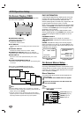
Without Cable Box
If your cable wire is connected to your TV without a converter
or descrambler box, unscrew the wire from your TV and attach
it to the ANT.IN jack on the DVD+VCR. Use the supplied round
coaxial cable to connect between the DVD+VCR’s RF.OUT
jack and the 75 ohm antenna input jack on the TV. With this
connection, you can receive all midband, super band, and
hyperband channels.
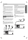
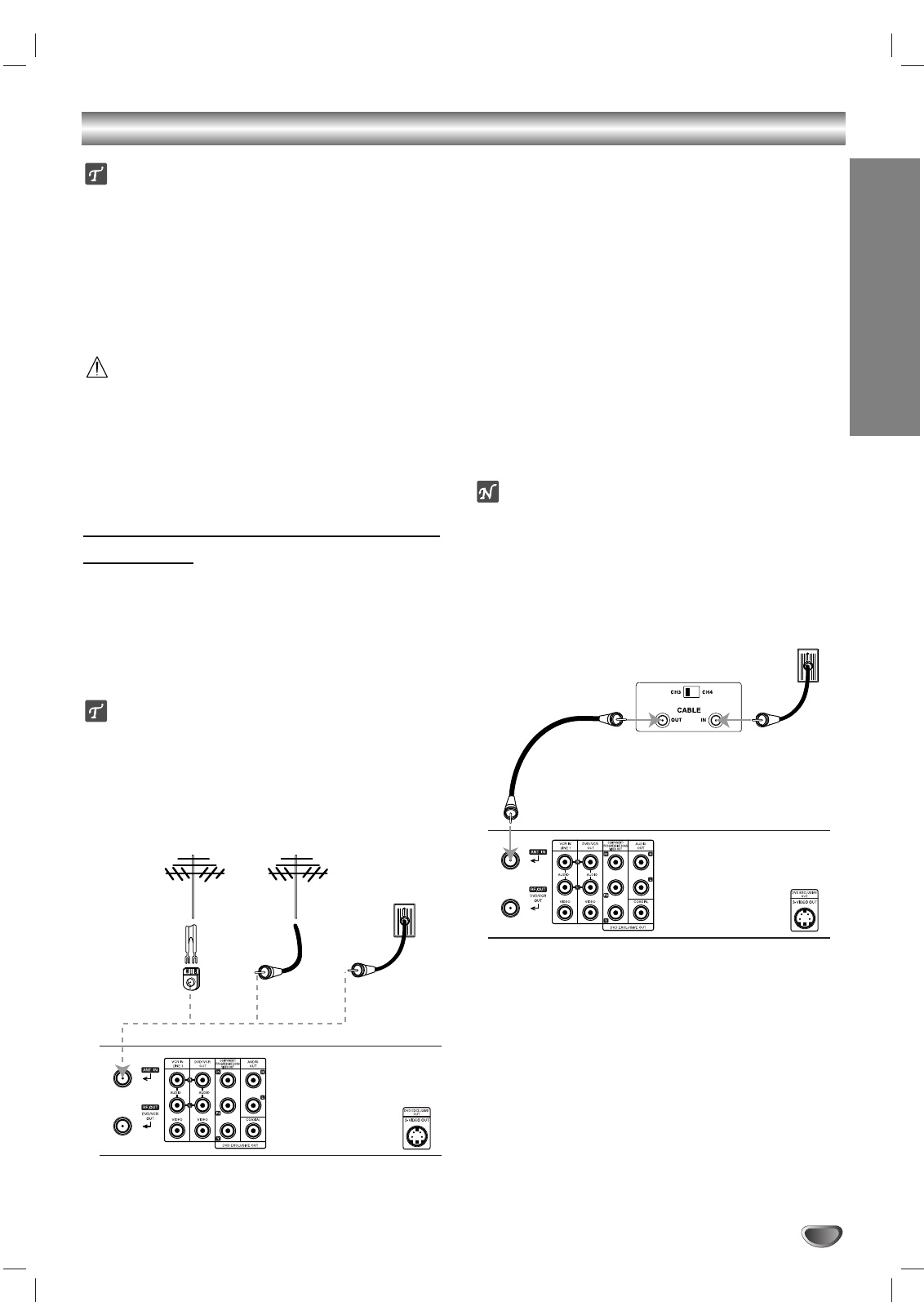
With Cable Box
If a converter is required in your cable system, follow the
instruction below:
The cable hookup permits both TV and DVD+VCR operation.
To view or record CATV channel
1 Tune the TV to the DVD+VCR output channel (CH 3 or 4).
2 Set the DVD+VCR channel selector to the output channel of
the Cable Converter box by using the CH/TRK (v/V) or
number (0-9) of your DVD+VCR. (Example: CH3)
3 Select the channel to view at the Cable Converter Box.
otes
With this connection, you CANNOT record one program
while viewing another.
If you are using a cable box to tune channels, it is not nec-
essary to do Auto Channel Programming as indicated on
page 15.
Antenna Antenna
Flat Wire
(300 ohm)
300/75 ohm
Adaptor
(Not supplied)
Cable TV
Wall Jack
OR OR
Rear of DVD+VCR
Cable TV
Wall Jack
Back Panel of
Typical Cable Box
Rear of DVD+VCR