!
62
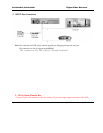
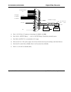
Fasten the transfer box on the back panel of DVR with two screws
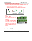
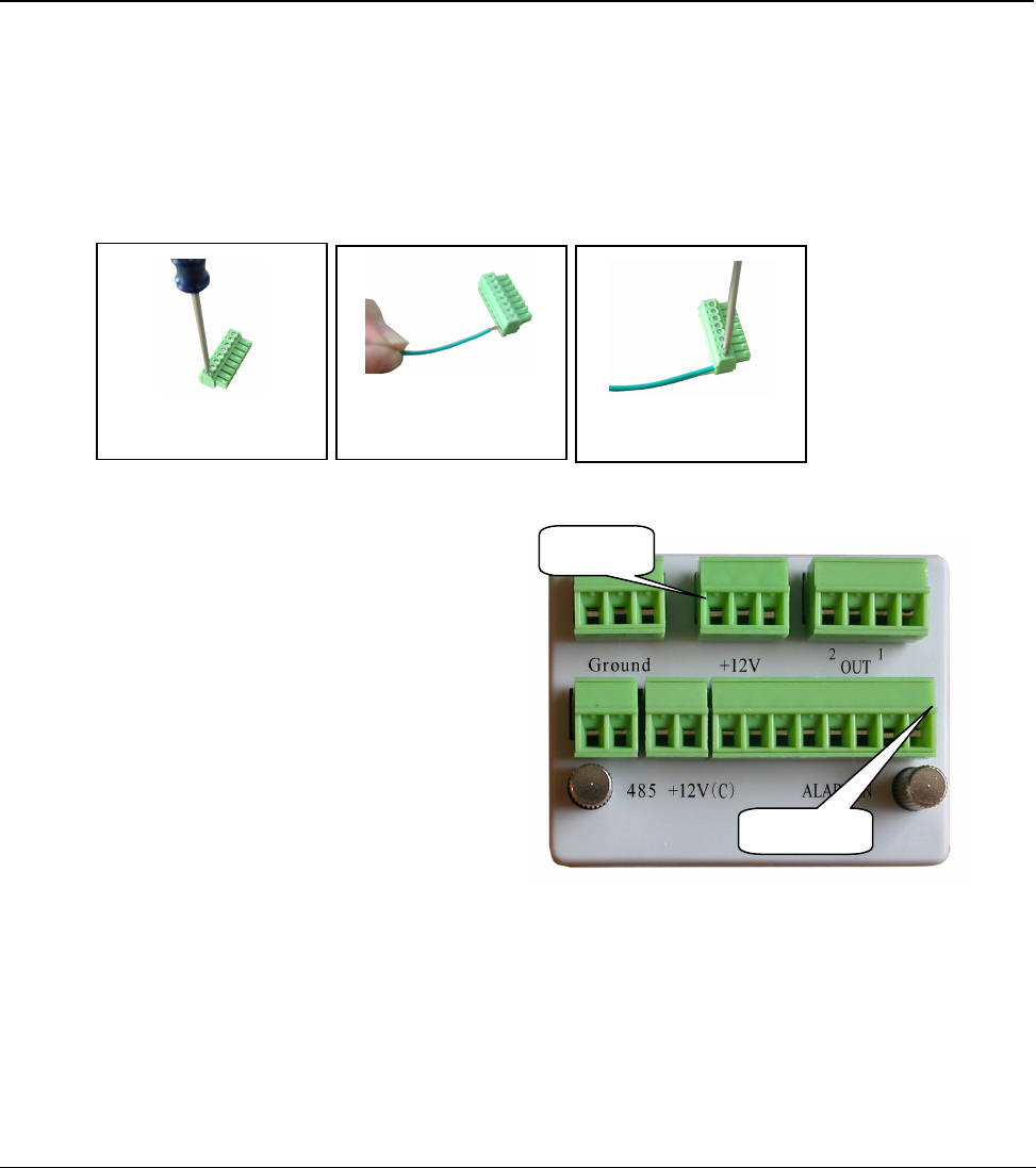
Pull out 6 connection terminals of the transfer box, corresponding connection marks can be clearly noticed.
Connect function line according to connection marks
Loosen the screws on the connection terminal;connection diagram
Insert lines needed to corresponding terminals connection diagram
Fasten the screws on the terminals after insertion of the lines.(connection diagram
Notes:
a) “Ground”ground line
b)“+12v”provide the power to alarm device
with current less than 2A
c)“OUT 12” is two alarm outputs switch.
Nomal open type
d)485 AB is communication connection,
used to connect such recorder control device
such as control decoder
e)+12C” is control power output, is used for
standby power for smoke sensor alarm device..
dismiss of the alarm needs the device to turn off
the power.
f)ALARMIN 1…8 is alarm input. High level voltage input. Input
voltage is 6-24V12V is recommended
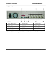
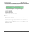
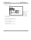
10-Pin connection for DVR1604RW
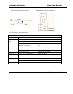
If you want to control pan-tilt, lens and process the relay of the alarming signals by the DVR, the 10-pin port can realize. The
connection diagram
screw
terminal
connection diagram
connection diagram


