


13
Operation Guide
Operation Guide
TAPE IN/OUTS
INPUT OUTPUT
INPUT OUTPUT
INPUT OUTPUT
ANALOG I/O ANALOG I/OANALOG I/O
OUT
IN
IN
IN
OUT
OUT
DIGITAL WORD CLOCK I/O MIDI
ADAT SYNC
IN
ADAT SYNC
OUT
SERIAL
9-PIN
FOOT
SWITCH
SMPTE
MICRO/
REMOTE 24
CNTRL
ANALOG OUT 1 - 8 ANALOG OUT 9 - 16 ANALOG OUT 17 - 24
ANALOG IN 1 - 8 ANALOG IN 9 - 16 ANALOG IN 17 - 24
RISK OF ELECTRIC SHOCK
DO NOT OPEN
REPLACE WITH THE SAME TYPE FUSE AND RATING.
DISCONNECT SUPPLY CORD BEFORE CHANGING FUSE
UTILISE UN FUSIBLE DE RECHANGE DE MÊME TYPE.
DEBRANCHER AVANT DE REMPLACER LE FUSIBLE
WARNING:
TO REDUCE THE RISK OF FIRE OR ELECTRIC SHOCK, DO NOT
EXPOSE THIS EQUIPMENT TO RAIN OR MOISTURE. DO NOT REMOVE COVER.
NO USER SERVICEABLE PARTS INSIDE. REFER SERVICING TO QUALIFIED PERSONNEL.
CAUTION
SERIAL NUMBER
MANUFACTURING DATE
AVI S:
RISQUE DE CHOC ELECTRIQUE — NE PAS OUVRIR
CONCEIVED, DESIGNED, AND MANUFACTURED BY MACKIE DESIGNS INC • WOODINVILLE • WA 98072 • USA
MADE IN USA • FABRIQUE AU USA • PATENTS PENDING COPYRIGHT ©1998 THE FOLLOWING ARE TRADEMARKS OR
REGISTERED TRADEMARKS OF MACKIE DESIGNS INC.: "MACKIE.", MACKIE DIGITAL SYSTEMS AND THE "RUNNING MAN" FIGURE.
POWER
USB
1 - 8
IN OUT
DIGITAL
9 - 16
IN OUT
DIGITAL
17 - 24
X2
1-4
X2
5-8
X2
9-12
IN OUT
24 TRACK/24 BIT DIGITAL
AUDIO RECORDER
HIGH RESOLUTION
NON-LINEAR RECORDER
96
SDR
100 - 240V 250mA
50/60Hz
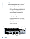
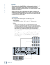
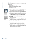
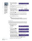
2. Connect three break-out cables to the SDR24/96 Outputs (top connectors).
Connect the plug end of the cables to the like-numbered Tape Return jacks
on the 24•8 console.
SDR24/96 Settings
1. Set the Sample Clock (SETUP:Sync:SClk) to Internal.
2. Set the Sample Rate and Sample Size according to your preference.
Console Settings
Set the 24•8 console to the nominal +4 dBu operating level by setting the five
Operating Level switches in the Sub Out and Tape Return sections to the ‘out’
position.
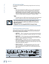
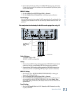
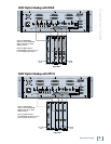
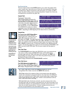
This example describes the hookup for the D8B console equipped for analog I/O.
(6) DB25 to
DB25 Analog
Cables
Digital 8•Bus
SDR 24/96
AIO•8 Cards
Cables & Hardware
(3) AIO•8 cards for D8B
(6) DB25 to DB25 analog cables
Hookup
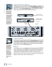
1. Connect three DB25 analog cables between the SDR24/96 Inputs (bottom
connector) and the corresponding D8B Tape Outputs (top connector).
2. Connect three DB25 analog cables between the SDR24/96 Outputs (top
connector) and the corresponding D8B Tape Inputs (bottom connector).
SDR24/96 Settings
1. Set the Input Type (SETUP:I/O:INPUT TYPE SELECT) to Analog for
Inputs 1-8, 9-16, and 17-24.
2. Set the Sample Clock (SETUP:Sync:SClk) to Internal.
3. Set the Sample Rate and Sample Size according to your preference. It is
not necessary to set the D8B and SDR24/96 to the same Sample Rate,
since with analog connections, the sample clocks on the two units are not
synchronized
Console Settings
1. Set the D8B Sample Clock to 44.1 k Internal or 48 k Internal according
to your preference.