


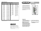
Front Panel Features
UP/DOWN VOLUME CONTROL
Use to adjust the level for the Input,
Output, or Group assigned to the remote
control. Duplicates the function of the UP/
DOWN buttons on the DX8 front panel.
LED DISPLAY
Indicates the level setting of the Input,
Output, or Group assigned to the remote
control. "0" corresponds to "10" on the
DX8 front panel LED display, which is unity
gain. "+10" corresponds to "OL" on the
DX8 front panel LED display, which is
maximum gain.
Rear Panel Features
PREDEFINED FUNCTION SELECTION SWITCH
This 8-position DIP switch provides 256
unique functions that can be assigned to
the DX-RVC remote. Refer to the chart on
the back page for a list of all predefined
functions currently available.
Each remote control must have the
selection switch set to a unique ID. When
the DX8 is first turned on, it polls the
REMOTE BUS
and identifies the remote
controls connected to it by each unique ID.
Many of the predefined functions have
two ID addresses assigned to it to allow
two remote controls to be connected to a
DX8 that both control the same function.
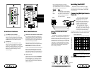
CONNECTOR (J2)
Connect the wires from the DX8
REMOTE
BUS
directly to this connector. Strip the
wire back about 1/4", insert the wire as
far as it will go into the connector and
tighten down the screw with a small slot-
head screwdriver.
Use a high-quality three-conductor
shielded cable to make this connection,
such as Belden 8451, 9451, or equivalent.
The connector is wired as follows:
Remote DX8
GND G (Ground)
A + (+ Data with +24V DC power)
B – (– Data with +24V DC power)
PWR N/C (This is for an external
power supply, described in
the next section)
R20
R21
R22
R23
R24
R25
R26
R27
C14
C7
R35
R1
R2
R3
C3
C4
C16
R34
R4
D3
D4
C9
U5
U2
C8
U6
J2
L2 L1
J4
S1
D2
J5
J3
R6
R7
C10
R5
GND
A
B
PWR
1
ON
FUNCTION
2345678
Installing the DX-RVC
The DX-RVC can be installed in a single
standard electrical box, or in a double-gang
box along with a second DX-RVC or DX-SW4
remote control.
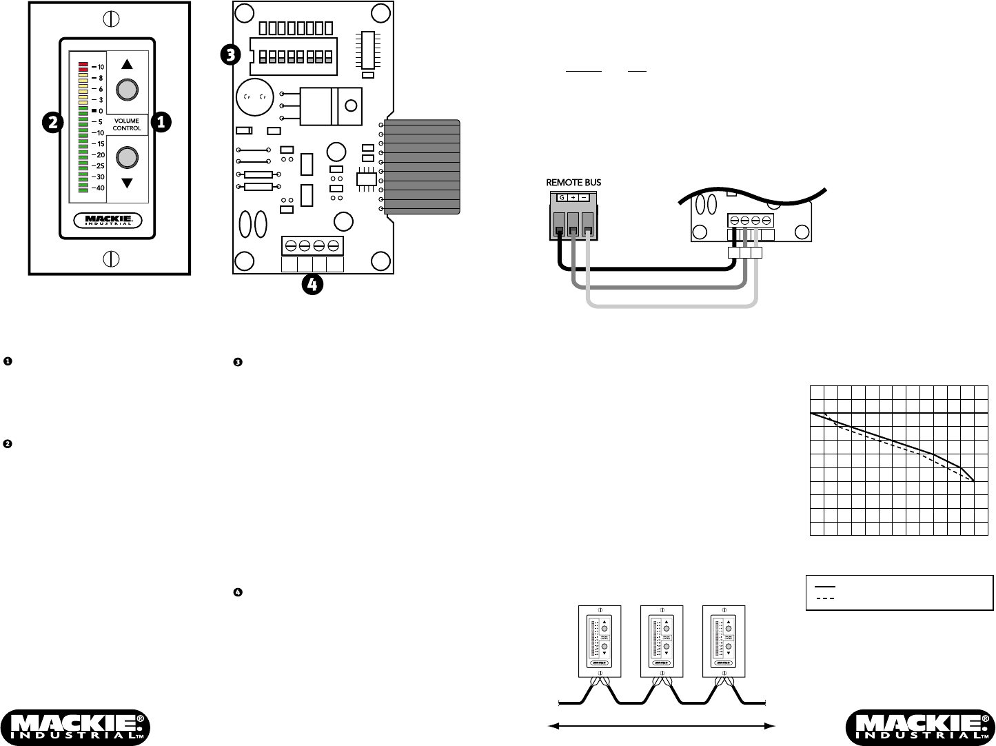
Connecting Multiple Remote
Controls
Up to nine remote controls
can be connected to the DX8
REMOTE BUS
. The maximum
length of the cable depends on
the type of cable used and the
number and type of remote
controls used in the system.
As a general rule, using 22
gauge wire (at 0.014 Ω /ft. and
34 pF/ft.), one remote can be up
to 3000 feet away, five remotes
can be up to 2500 feet away,
and eight remotes can be up to 500 feet away
before transmission losses become a factor.
To Next Remote
Total Distance Dependent on Type of Cable Used
From DX8
C8
J2
L2 L1
R5
GND
A
B
PWR
GND
A
B
DX8 DX-RVC
Using an External Power
Supply
The DX-RVC is powered by the DX8 over the
data lines. An external power supply can be
used by removing jumpers J3 and J5 from the
DX-RVC circuit board, and connecting a power
supply rated at 9 to 16V AC or DC to the PWR
terminal on the connector (J2). A number of
"wall-warts" or bell transformers are readily
available from local electrical supply houses
with output ratings between 9V and 16V.
Allow 25mA per remote.
Distance Chart for DX-RVC Cable
Feet of Cable versus
Maximum Number of 2-Button Remotes
Feet of Cable
Belden 8451 (22 AWG, 34pf/ft)
Belden 1192A (24 AWG, 39pf/ft)
0
0
250
500
750
1000
1250
1500
1750
2000
2250
2500
2750
3000
3250
1
2
3
4
5
6
7
8
9
10
Number of 2-Button Remotes