


• Cost effective solution for DTV and Multimedia Applications
• Converts Composite Video or Y/C to Digital Component (SDI)
• NTSC or PAL operation with automatic detection
• Illuminated power and input signal indicators
• Adaptive filtering removes NTSC interlace artifacts
• 2 x over sampling for true color reproduction
• 12 Bit analog to digital conversion
• 10-bit qauntization of output signal
• 1 line process delay
• Includes color bar generator
• Includes Power Supply Model V-PS6-1.2A
1
Product Overview
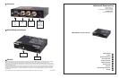
The BC-0103-10 is a Composite Video or Y/C (S-Video) (NTSC/PAL) to Serial Digital Interface (SDI) conversion module. Fea-
turing automatic cable compensation, 12-bit processing and a superior adaptive comb fi lter, the Bc-0103-10 is an ideal solution
for critical DTV applications and facility transitions to a digital environment. There is also a built in Color Bar Generator, System
indicator (PAL/NTSC), and dipswitch settings for Pedestal (On/Off), Adaptive Comb Filter (On/Off), Input signal AGC (On/Off)
and White Peak. All Marshall Electronics Processing and Distribution modules include power supply and owners manual.
An optional base holder (V-CB1) is available for use in desktop applications plus two options for 19” rack mounting (V-CRM2
and V-CRM-3).
2
Features
3
Electrical Specifications
Signal Input BNC for Composite Video 75Ω, 4 pin mini-din Y/C Video
Signal Output 2 BNC SDI 10 bit Component Digital (SMPTE-259M/ITU-R BT601)
Sample Frequency 27mhz
K factor <1%
Signal to Noise >63 db
Differential gain/phase 0.4% / 0.60
Input Cable length Up to 1000ft (300m) AGC compensated - (Belden 8281 typical)
Power required 6 V D.C. from external power supply (included) max 1.2 AMP
2
3
BC-0103-10
BC-0103-10
Users Guide
Users Guide
Marshall Electronics
7
Operational Setup
Power required 6V D.C. from external supply 3.0 Amp max
Dimensions 4.75”W x 3.75”D x 1.0”H
Weight 0.55 lbs
4
General Information
5
Included Accessories
Power Supply (Class 2) Desktop Stand (Model V-CB1)
Users Guide 3 Module Rack Mount Kit (Model V-CRM3)
Weight Wall Mount Brackets
Desktop Stand (Model V-CB1)
Optional Accessories
7
6
A.
B.
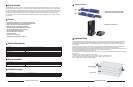
1. Unpack the BC-0103-10 and accompanying V-PS6-1.2A power supply. Physically inspect for any damage that may have
occurred during shipping. Also verify there is a small package with mounting accessories. Should there be any damage,
immediately contact Marshall Electronics at 800-800-6608. If you are not located within the continental united states call +1
310-333-0606.
2. Install in your desired location. If wall mounting is required, attach the mounting brackets by removing the Phillips head
screws on the sides, closest to the rear of the unit. (See Below) Only one screw per side should be removed.
Use the same screw to attach the bracket with the fl ange facing away from the side and parallel to the front of the BC-0103-10
metal case. The fl ange has two holes. For desktop use, apply the supplied rubber pads.
3. Connect required cables for signal input and output.
Please note that power must be applied to the BC-0103-10 for the SDI Output to be activated. All BNC connectors should be
rated for 75
Ω.
3. Plug the V-PS6-1.2A power supply into the A.C. source
4. Attach twist lock power connection from V-PS6-1.2A power supply to the back of the unit.
5. Turn on the BC-0103-10 by depressing the power switch located on the front of the unit.
Refer to Page 4 picture for location of switch settings.
Bracket Installation
Feet Installation
A. 2 Module Rack Mount Kit (Model V-CRM2)
B. 3 Module Rack Mount Kit (Model V-CRM3)