


1. Unpack the BC-0909-DA and accompanying V-PS6-1.2A power supply. Physically inspect for any damage that may have occurred during ship-
ping. Also verify there is a small package with mounting accessories. Should there be any damage, immediately contact Marshall Electronics at
800-800-6608. If you are not located within the continental united states call +1 310-333-0606.
2. Install in your desired location. If wall mounting is required, attach the mounting brackets by removing the Phillips head screws on the sides,
closest to the rear of the unit. (See Below) Only one screw per side should be removed.
Use the same screw to attach the bracket with the flange facing away from the side and parallel to the front of the BC-0909-DA metal case. The
flange has two holes. For desktop use, apply the supplied rubber pads.
3. Connect required cables for signal input and output.
Please note that power must be applied to the BC-0909-DA
for the Analog Output and HDSDI/SDI Loop out to be
activated. All BNC connectors should be rated for 75Ω.
3. Plug the V-PS6-1.2A power supply into the A.C. source
4. Attach twist lock power connection from V-PS6-1.2A
power supply to the back of the unit.
5. Turn on the BC-0909-DA by depressing the power
switch located on the front of the unit.
Refer to Page 4 picture for location of switch settings.
Operational Setup
7
6
1910 East Maple Ave. El Segundo, CA 90245 • Tel.: 800-800-6608 • Fax:310-333-0688 • www.LCDRacks.com • Email: sales@lcdracks.com
BC-0909-DA Universal Digital Converter Users Guide
7
8
Warranty
Marshall Electronics warranties to the fi rst consumer, that this BC-0909-DA Digital to Analog Converter will, under normal use be free from defects in workmanship and
materials, when received in its original container, for a period of one year from the purchase date.
This warranty is extended to the purchasing end user only and proof of purchase is necessary to honor the warranty. If there is no proof of purchase provided with a
warranty claim, Marshall Electronics reserves the right not to honor the warranty set forth above. Therefore, labor and parts may be charged to you.
This warranty does not apply to product exterior and cosmetics. Misuse, abnormal service or handling, improper alterations or modifi cations in design or construction,
voids this warranty. No sales personnel of the seller, nor any other person is authorized to make any warranties other than those described above, or to extend the
duration of any warranties on behalf of Marshall Electronics, beyond the time period described above.
Due to constant effort to improve products and product features, specifi cations may change without notice.
7
7
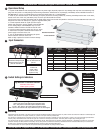
Input Connectors
HDSDI or SDI In
HDSDI or SDI Out Re-
Clocked and Shaped Signal
Requires Power to be ap-
plied for activation
Analog Signals Out
Refer to table below for
pin-out
6 VDC from
V-PS6-1.2A
power supply
Left Pin - Pos
Right Pin- Neg
Signal
Type
HD Analog
color difference
YPbPr
SD Analog color
difference
Y, R-Y, B-Y
S-Video
Y/C
HD or SD
Analog RGB
(Sync on Green)
Pin1 Pr R-Y C Red
Pin2 Y Y Y Green
Pin3 Pb B-Y Blue
Pin4
Pin5
Pin6 Ground Ground Ground Ground
Pin7 Ground Ground Ground Ground
Pin8 Ground Ground Ground
Pin9
HD-15
BNC Breakout
Red
Green
Blue
Ground
Ground
Ground
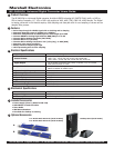
Switch Settings & Indicators
7
6
Output Signal Format
Video- Only active in SD mode output Composite Video
YUV – Only active in SD mode output Component Video
Y-Pr-Pb – Only active in HD mode output Component Video
RGB – Active in HD and SD mode output RGB with Sync on Green Signal
Power On/Off indicator
Input Signal Standard Indicator
High Defi nition or Standard Defi nition
Illuminates when SDI or
HDSDI signal is present
Bracket Installation
Feet Installation