


V-R70P-SD Users Guide
Marshall Electronics
The V-R70P-SD features Marshall’s proprietary TFT-MegaPixel™ display system and represents leading edge technology in LCD
imaging for broadcast and professional video applications. This is a low cost stand alone monitor and is constructed with a durable
enclosure featuring an optical grade polycarbonate protective cover for the antiglare/antireflective screen. A V-Mount battery adapt-
er is also included and the monitor can be powered for over 5 hours with a 50WH battery. The 1.2-million pixel TFT screen has 130
degree viewing angles and incorporates completely digital signal processing to provide image reproduction that exceeds all CRT
displays available in a similar form factor. All SMPTE/ITU High Definition and Standard Definition digital video standards and signal
types are accepted and displayed on this model. All video formats are scaled to fit on screen in the highest resolution using a state
of the art LSI that incorporates 4x4 pixel interpolations with precision Gamma correction to produce the best images available.
Additional features include, three LED tally, setup memory, Blue Gun, and direct access for all adjustment and selection functions.
1
Product Overview
2
Features
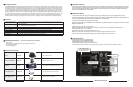
High Definition Displays Capable of displaying more than 900 TV Lines resolution. Standard definition is internally up converted to High
Definition. All signals remain completely digital to provide the most exact images available.
Standard Inputs
• SDI (SMPTE-259M)
• Analog Composite PAL/NTSC Auto Detect (BNC with loop out) (SMPTE170M)
• Y/C (S-video) (4 Pin Mini-din with loop out)
Durable metal enclosure • Protection for all connections and controls with strategically placed ventilation for use in harsh environments
Protective Screen Cover • Optical grade polycarbonate screen cover with Antireflective / Antiglare coating
Memory Function
• Adjustment Settings Memory stored on shutdown and recalled when power is applied
Blue Screen • Use for adjustment to SMPTE color Bars
Built in color bars • For screen testing purposes
Tally (DB-15) • Three LEDs (Red, Green, Amber) produce 7 different tally indications
3
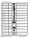
Standard Accessories
Accessories Supplied with the V-R70P-SD
4
Optional Accessories
Stand V-LCD4-ST Use for table top mount
Camera Hot Shoe Mount V-LCD4-MT Attaches monitor to camera
Sun Hood V-H700P Use for viewing in bright lighting or outdoors
Power Adapter Cable V-PAC-D-XLR Use with Anton Bauer D-type connection
Power Adapter Cable V-PAC-XLR-1 Use with 4 Pin XLR connections
2
5
• Users manual
• “Brick” type 12vdc power supply with 4 Pin Female XLR connector
• “V” Mount battery adapter
• ¼”-20 mounting plate
7
Faceplate Cleaning
When cleaning the faceplate it is very important to use non-abrasive and ammonia free cleaning agents and a clean
micro fiber clothe, or cheese clothe. Do not use paper towels. Paper towel fibers are coarse and may scratch the sur-
face of the Polycarbonate faceplate. Paper towels may also leave streaks on the surface. Antistatic and fingerprint
resistant cleaning agents are recommended.
1. Unpack the V-R70P-SD and accompanying power supply. Physically inspect for any damage that may have
occurred during shipping. Should there be any damage, immediately contact Marshall Electronics at 800-800-6608. If
you are not located within the continental united states call +1 310-333-0606.
2. Connect required cables for signal input and output.
Please note that power must be applied to the V-R70P-SD for the SD/SDI outputs to be activated. All BNC connectors
should be rated for 75
Ω..
3. Plug the power supply into the A.C. source
Please note that power can be supplied from a variety of DC sources, such as batteries or Vehicle power.
Input power range is 10.7 to 15 Volt D.C.
In operation, the V-R70P-SD will draw approx. 0.8 amp.
Attach 4 Pin XLR power connection from V-PS12-V-5 power supply to the back of the unit.
4. Turn on the V-R70P-SD by depressing the power switch located on the front of the unit.
8
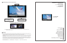
Operational Setup
* Composite Video Inputs comply to SMPTE-170M
* Component Inputs comply to SMPTE274M, 294M
* Outputs Require Power to be applied for activation
* Battery and External Power can not be used simultaneously
* Active Outputs require power to be applied. All input signals appear as output signal. Analog output signals are buffered and amplifi ed.
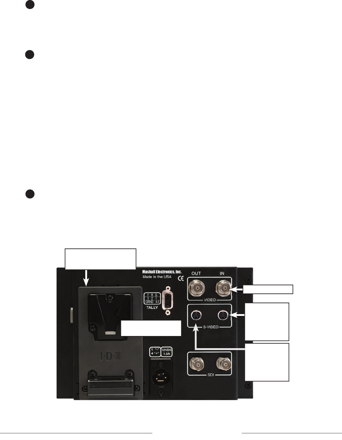
Composite Video In
S-Video Out
4 Pin Din (Female)
Pin1 - GND
Pin2 - GND
Pin3 - Yout
Pin4 - Cout
Input Connectors
9
V - Mount Battery Adapter.
See Optional Accessory section
for a selection of batteries
S-Video In
4 Pin Din (Female)
Pin1 - GND
Pin2 - GND
Pin3 - Yin
Pin4 - Cin
Tally lamps active when
connected to ground