


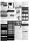

Specifications are subject to change without notice
HEAD OFFICE : MITSUBISHI DENKI BLDG MARUNOUTI TOKYO 100-8310
HIMEJI WORKS : 840, CHIYODA CHO, HIMEJI, JAPAN
When exported from Japan, this manual does not require application to the Ministry of Economy,
Trade and Industry for service transaction permission.
Even while an upper/lower limit value error is detected, the data (BFM #10
to BFM #13) of each channel continues to be updated.
Bit assignment of
BFM #26
BFM #27: A/D data sudden change detection status
The sudden change detection function (BFM#22 b2) writes detected errors
to the corresponding bits in BFM#27. The sudden change detection status
for negative or positive changes is located in the first 8bits of BFM#27 in
bit-pairs.
When the data (BFM #10 to BFM #13) of each channel is updated, if the
difference between the previous value and the new value is larger than the
sudden change detection set value (BFM #91 to BFM #94), the
corresponding bit in BFM #27 turns ON.
At this time, when the new value is larger than the previous value, a bit for
the + direction turns ON. when the new value is smaller than the previous
value, a bit for the - direction turns ON.
When a bit turns ON, it remains ON until it is reset by BFM #99 or the
power is turned OFF.
Even while a sudden change error is detected, the data (BFM #10 to BFM
#13) of each channel continues to be updated.
Bit assignment of
BFM #27
BFM #28: Scale over status
The result of the analog input value for each individual channel that has
exceeded the A/D conversion range will be written to BFM#28.
Range in which A/D conversion is available:
A bit will remain ON unless it is reset from switching the Power OFF or
overwriting the ON bit with an OFF bit via a TO instruction.
Even while a scale over error is detected, the data (BFM #10 to BFM #13)
of each channel continues to be updated.
Bit assignment of
BFM #28
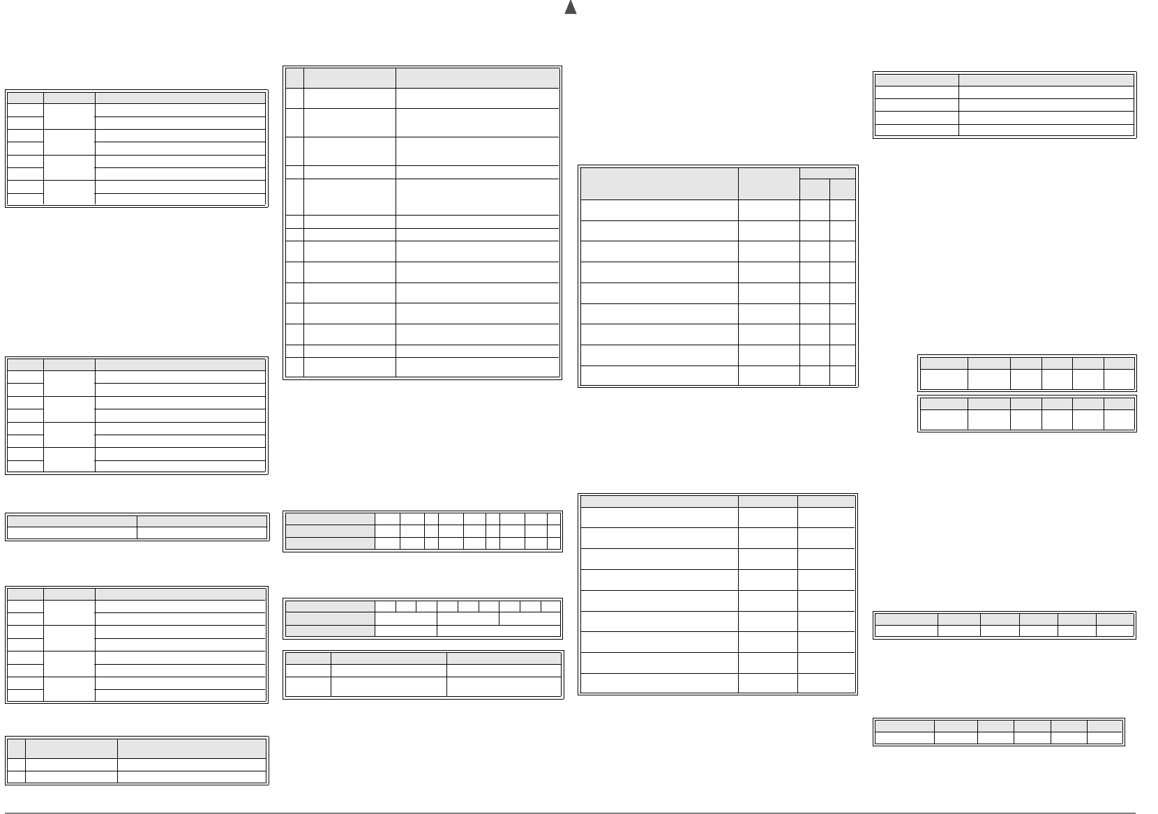
BFM #29: Error status
Error information is assigned to each bit of BFM #29.
Bit assignment of
BFM #29
Bit No. Channel No. Description
b0
CH1
Lower limit error
b1 Upper limit error
b2
CH2
Lower limit error
b3 Upper limit error
b4
CH3
Lower limit error
b5 Upper limit error
b6
CH4
Lower limit error
b7 Upper limit error
Bit No. Channel No. Description
b0
CH1
Sudden change error in - direction
b1 Sudden change error in + direction
b2
CH2
Sudden change error in - direction
b3 Sudden change error in + direction
b4
CH3
Sudden change error in - direction
b5 Sudden change error in + direction
b6
CH4
Sudden change error in - direction
b7 Sudden change error in + direction
Voltage input mode Current input mode
- 10.2V to 10.2V - 20.4mA to 20.4mA
Bit No. Channel No. Description
b0
CH1
Scale over: Less than lower limit
b1 Scale over: More than upper limit
b2
CH2
Scale over: Less than lower limit
b3 Scale over: More than upper limit
b4
CH3
Scale over: Less than lower limit
b5 Scale over: More than upper limit
b6
CH4
Scale over: Less than lower limit
b7 Scale over: More than upper limit
Bit
No.
Assignment Description
b0 Error detected b0 is ON while either b2 to b4 is ON.
b1
BFM #30: Model code
BFM #30 stores a fixed value of "K2070".
BFM #32: Operating time
BFM #32 stores the continuous operating time for the FX
2NC
-4AD.
Measurement starts when the power is turned ON, and the measured value is
reset when the power is turned OFF.
The measurement range is from 0 to 64,800 (s). After that, 64,800 is kept.
BFM #41 to BFM #44: Offset data
BFM #51 to BFM #54: Gain data
Offset data:Analog input value when the digital value is "0"
Gain data :Analog input value when the digital value is as shown below (The
digital value varies depending on the setting of the input mode.)
Standard digital value for offset and gain in each input mode
(A number in the input mode column indicates a value set in BFM #0.)
• Set the offset and gain data for each channel.
• Write the set value in units of "mV" for voltage input or "
µ
A" for current input.
• Do not change the input characteristics when
!
=
2, 5, 8 is set in BFM #0.
(Even if a numerical value is written, it is ignored.)
Initial offset/gain value (Unit: mV for voltage input,
µ
A for current input)
Setting range
The actual effective input range is "-10 to 10 V" or "-20 to 20 mA".
BFM #61 to BFM #64: Addition data
When using the data addition function (BFM #22 b0), data (BFM #10 to BFM
#13), minimum/maximum value (BFM #101 to BFM #104, BFM #111 to BFM
#114) and data history (BFM #200 to BFM #1799) of each channel becomes the
measured value added by the addition data (BFM #61 to BFM #64).
When using the data addition function, enter the value added by the addition
data (BFM #61 to BFM #64) to the lower limit value error set value (BFM #71 to
BFM #74) and the upper limit value error set value (BFM #81 to BFM #84).
Setting range: -16,000 to 16,000
Bit
No.
Assignment Description
b2 Power error
24V DC power is not correctly supplied.
Check the wiring and supply voltage.
b3 Hardware error
FX
2NC
-4AD may have malfunctioned.
Contact the nearest Mitsubishi Electric System
Service center.
b4
A/D conversion value
error
A/D conversion value is abnormal.
Using the scale over data (BFM #28), check the
channel in which the error has occurred.
b5
b6 BFM read/write disabled
This bit will be ON during the input
characteristics change processing. While this bit
is ON, correct A/D data will not read from or
written to BFMs.
b7
b8 Set value error detected This bit will be ON while either b9 to b15 is ON.
b9 Input mode setting error
Input mode (BFM #0) is incorrectly set.
Set it within the range from 0 to 8.
b10
Number of averaging
times setting error
Number of averaging times is incorrectly set.
Set it within the range from 1 to 4,095.
b11 Digital filter setting error
The digital filter setting is incorrect.
Reset within the range of 0 to 1,600.
b12
Sudden change detection
set value error
Sudden change detection set value is incorrect.
Set a correct value.
b13
Upper/lower limit set value
error
Upper/lower limit set value is incorrect. Set a
correct value.
b14
b15 Addition data setting error
Addition data is incorrectly set.
Set it within range from -16,000 to 16,000.
Input mode (BFM #0) 012345678
Standard offset value 00-00-00-
Standard gain value 16000 2000 - 16000 4000 - 16000 4000 -
Input mode (BFM #0) 012345678
Initial offset value 0 4000 0
Initial gain value 5000 20000
Voltage input Current input
Offset data -1000 to 9000 (mV) -20000 to 17000 (µA)
Gain data
Gain value - Offset value
= 1,000 to 10,000 (mV)
Gain value - Offset value
= 3,000 to 30,000 (µA)
BFM #71 to BFM #74: Lower limit, error set value
BFM #81 to BFM #88: Upper limit, error set value
When using the upper/lower limit value detection function (BFM #22 b1), write
the lower limit value of each channel to BFM #71 to BFM #74 and the upper limit
value of each channel to BFM #81 to BFM #84.
When using the data addition function (BFM #22 b0), enter the value added by
the addition data to BFM #61 to BFM #64.
Setting range
The setting range will vary depending on the setting of the input mode (BFM #0).
The table below shows the setting range for each input mode. Enter the set
value as a digital value.
BFM #91 to BFM #94: Sudden change detection set value
When using the sudden change detection function (BFM #22 b2), enter the set
value to judge the sudden change.
When the data (BFM #10 to BFM #13) of each channel is updated, if the
difference between the previous value and the new value is larger than the
sudden change detection set value (BFM #91 to BFM #94), the result is written
to the sudden change detection status (BFM #27).
Setting range
The setting range will vary depending on the setting of the input mode (BFM #0).
The table below shows the setting range for each input mode.
Write the set value in a digital value.
BFM #99: Clears upper/lower limit value error and sudden change
detection error
The commands to clear the lower and upper limit value error and the sudden
change detection error are assigned to the lower three bits of BFM #99.
The flag of the corresponding error status (BFM #26, BFM #27) is reset for all
channels simultaneously when a bit is set to ON.
After the reset is finished, each bit of BFM #99 returns automatically to the OFF
state.
The setting of two or more clear commands to ON at the same time is possible.
Input mode (BFM #0) Setting range
Initial value
Lower
limit
Upper
limit
0: Voltage input mode
(-10 to 10 V → -32000 to 32000)
-32768 to 32767 -32768 32767
1: Voltage input mode
(-10 to 10 V → -4000 to 4000)
-4096 to 4095 -4096 4095
2: Voltage input mode
(-10 to 10 V → -10000 to 10000)
-10200 to 10200 -10200 10200
3: Current input mode
(4 to 20 mA → 0 to 16000)
-1 to 16383 -1 16383
4: Current input mode
(4 to 20 mA → 0 to 4000)
-1 to 4095 -1 4095
5: Current input mode
(4 to 20 mA → 4000 to 20000)
3999 to 20400 3999 20400
6: Current input mode
(-20 to 20 mA → -16000 to 16000)
-16384 to 16383 -16384 16383
7: Current input mode
(-20 to 20 mA → -4000 to 4000)
-4096 to 4095 -4096 4095
8: Current input mode
(-20 to 20 mA → -20000 to 20000)
-20400 to 20400 -20400 20400
Input mode (BFM #0) Setting range Initial value
0: Voltage input mode
(-10 to 10 V → -32000 to 32000)
1 to 32767 3200
1: Voltage input mode
(-10 to 10 V → -4000 to 4000)
1 to 4095 400
2: Voltage input mode
(-10 to 10 V → -10000 to 10000)
1 to 10000 1000
3: Current input mode
(4 to 20 mA → 0 to 16000)
1 to 8191 800
4: Current input mode
(4 to 20 mA → 0 to 4000)
1 to 2047 200
5: Current input mode
(4 to 20 mA → 4000 to 20000)
1 to 8191 800
6: Current input mode
(-20 to 20 mA → -16000 to 16000)
1 to 16383 1600
7: Current input mode
(-20 to 20 mA → -4000 to 4000)
1 to 4095 400
8: Current input mode
(-20 to 20 mA → -20000 to 20000)
1 to 20000 2000
Bit assignment of BFM #99
BFM #101 to BFM #104: Minimum value
BFM #111 to BFM #114: Maximum value
When using the minimum/maximum value hold function (BFM #22 b3), the
minimum value of the data (BFM #10 to BFM #13) of each channel is
written to BFM #101 to BFM #104, and the maximum value is written to
BFM #111 to BFM #114.
When using the data addition function (BFM #22 b0), the minimum/
maximum measured value will be added to the addition data (BFM #61 to
BFM #64).
Initial value
Minimum/maximum value hold function is not used:K0
Minimum/maximum value hold function is used: Digital value when the
power is turned ON
BFM #109: Minimum value reset
BFM #119: Maximum value reset
When using the minimum/maximum value hold function (BFM #22 b3),
BFM #109 clears the minimum value stored in BFM #101 to BFM #104,
and BFM #119 clears the maximum value stored in BFM #111 to BFM
#114.
The channel No. that will be reset is assigned to each bit of BFM #109 and
BFM #119. When a bit is set ON, minimum/maximum value of the assigned
channel is cleared. (Setting two or more bits ON simultaneously is
possible.)
Bit assignment
BFM #198: Data history sampling time
Set the data history sampling time.
Setting range: 0 to 30,000 ms
Sampling cycle
When the set value is "0" :1 ms x Number of effective channels
When the set value is "1" or more:Set value (ms) x Number of effective
channels
BFM #199: Resets or stops data history
The data history reset function is assigned to the lower 4 bits of BFM #199.
The data history stop function is assigned to the upper 4 bits of BFM #199.
Data history reset function
This function clears the sampled data history for each channel.
The channel No. to be reset is assigned to each of the lower 4 bits of BFM
#199.
When a bit is set to ON, the data history (all contents from the 1st value to
the 400th value) of the assigned channel is cleared. (The setting of two or
more bits to ON simultaneously is possible.)
When the clear operation is completed, each bit returns automatically to
the OFF state.
Assignment of lower 4 bits
Data history stop function
This function will temporarily stop the data history for the individual
channels. The channel No. to be temporarily stopped is assigned to each
of the upper 4 bits of BFM #199. When a bit is set to ON, sampling of the
data history of the assigned channel is temporarily stopped. (Setting two or
more bits to ON at a time.)
When a bit is set to OFF, sampling of the data history of the assigned
channel restarts.
Assignment of upper 4 bits
Bit No. Description
b0 Clears lower limit error.
b1 Clears upper limit error.
b2 Clears sudden change detection error.
b3 to b15 Unusable
BFM #109
Bit No. b15 to b4 b3 b2 b1 b0
Channel No.
(BFM No.)
Unusable
CH4
(#104)
CH3
(#103)
CH2
(#102)
CH1
(#101)
BFM #119
Bit No. b15 to b4 b3 b2 b1 b0
Channel No.
(BFM No.)
Unusable
CH4
(#114)
CH3
(#113)
CH2
(#112)
CH1
(#111)
Bit No. b7 to b4 b3 b2 b1 b0
Channel No. Unusable CH4 CH3 CH2 CH1
Bit No. b15 to b12 b11 b10 b9 b8
Channel No. Unusable CH4 CH3 CH2 CH1
BFM #200 to BFM #1799: Data history
The A/D conversion value of each channel is sampled, and written to the
BFMs shown below. The table below shows the assignment between the
channel No. and the BFM No. Data is stored in ascending order of the BFM
No.
Up to 400 data history items are written for each channel. When the
number of history items exceeds 400, the data is overwritten starting from
the smallest BFM No.
The data history function is valid only for channels whose number of
averaging times (BFM #2 to #5) is set to "1" and digital filter setting (BFM
#6 to #9) is set to "0".
Assignment of channel No. and BFM No.
• If a considerable amount of data history is read from the PLC main unit
using a FROM instruction, a watch dog timer error occurs in the PLC
main unit.
In such a case, divide the required data history using multiple FROM
instructions, and insert the WDT instruction (watch dog timer refresh
instruction) after each FROM instruction.
7. Adjustment of I/O Characteristics
For factory default, the FX
2NC
-4AD has standard I/O characteristics in
accordance with each input mode (BFM #0).
In the voltage and current input mode, adjust the standard I/O
characteristics for each channel. (Do not change the input characteristics
when 2, 5, 8 is set in BEM #0.)
7.1 Standard I/O characteristics
The input mode of the standard I/O characteristics is abbreviated as shown
below:
Channel
No.
BFM No.
1st value 2nd value 3rd value • • • • • 400th value
CH1 #200 #201 #202 • • • • • #599
CH2 #600 #601 #602 • • • • • #999
CH3 #1000 #1001 #1002 • • • • • #1399
CH4 #1400 #1401 #1402 • • • • • #1799
Digital value
-10
10
4,000
Approx. 4,080
Approx.
10.2 V
Approx.
-10.2 V
-4,000
Approx. -4,080
Input
voltage
(V)
0. Voltage input, -10 to 10V, -32,000 to 32000
➀
➁
➂
➃
➀
➂
: Input mode set in BFM #0
: Analog input range
0. Voltage input, -10 to 10 V,
-32,000 to 32000
1. Voltage input, -10 to 10 V,
-4000 to 4000
Digital value
-10
10
32000
Approx. 32640
Approx.
10.2 V
Approx.
-10.2 V
-32000
Approx. -32640
Input
voltage
(V)
➁
➃
: Input mode
: Digital output range
Digital value
-10
10
10,000
Approx. 10,200
Approx.
10.2 V
Approx.
-10.2 V
-10,000
Approx.
-10,200
Input
voltage
(V)
Digital value
Input current
(mA)
04 20
16000
2. Voltage input, -10 to 10V,
-10,000 to 10,000
3. Current input, 4 to 20 mA,
0 to 16000
7.2 Adjustment of I/O characteristics
Adjust the I/O characteristics using the buffer memories in the FX
2NC
-4AD.
Firstly, enter the input mode to BFM #0, then enter the offset data to BFM #41 to
BFM #44, subsequently enter the gain data to BFM #51 to BFM #54.
Update the offset data and the gain data for each channel using BFM #21.
Example program (Adjustment of CH1, CH2 and CH4)
*1 It takes approximately 5 seconds to change the input mode (BFM #0) (to
change each set value).
Assure that a time interval of 5 seconds or more is held after a change of the
input mode until execution of write of each setting (TO instruction).
• The I/O characteristics can be written (BFM #21) to either channel, or two or
more channels simultaneously.
Digital value
-20
20
16000
-16000
Input
current
(mA)
0
4. Current input, 4 to 20 mA,
0 to 4000
5. Current input, 4 to 20mA,
4,000 to 20,000
Digital value
Input current
(mA)
04 20
4,000
Digital value
Input current
(mA)
04 20
20,000
4,000
6. Current input, -20 to 20 mA,
-16000 to 16000
7. Current input, -20 to 20 mA,
-4000 to 4000
Digital value
-20
20
4,000
-4,000
Input
current
(mA)
0
Digital value
-20
20
20,000
-20,000
Input
current
(mA)
0
8. Current input, -20 to 20mA,
-20,000 to 20,000
X000
K0 K0 H1600 K1
K0 K41 K0 K2
K0 K51 K1250 K2
K0 K44 K0 K1
K0 K54
K10000
K1
K0 K21 H000F K1
Operation
start
instruction
Specifies the input
mode of CH1 to CH4.
Offset value of CH1
and CH2.
Gain value of CH1 and
CH2.
Offset value of CH4.
Gain value of CH4.
Offset value and gain
value of all channels at
a time.
M0
M0
SET
TO
K50
*1
T0
RST M0
FNC 79
TO
P
FNC 79
TO
P
FNC 79
TO
P
FNC 79
TO
P
FNC 79
TO
P
FNC 79
TO
P
8. Example program
This section introduces an example program to read analog data from the
FX
2NC
-4AD and connecting to digital data in the PLC.
Condition
System configuration:
The FX
2NC
-4AD is connected as a special function block nearest to the
FX
2NC
Series PLC main unit (unit No. 0).
Input mode:
CH1 and CH2: Mode 0 (voltage input, -10 to 10 V
→
-32000 to 32000)
CH3 and CH4: Mode 3 (current input, 4 to 20 mA
→
0 to 16000)
Number of averaging times:
1 (initial value) in each channel
I/O characteristics:
Standard I/O characteristics (initial value) in each channel
Convenient function:
Upper/lower limit value detection function is used.
Data history function:
Used while sampling time is set to 0ms (initial value).
CH1 to CH4: Sampling time = 1ms
×
4 (Number of effective channels) = 4ms
I/O assignment:
X001 : Clears the upper/lower limit value error.
X002 : Clears the scale over error.
Y000 to Y017: Output the upper/lower limit value error status of each
channel.
Y020 to Y037: Output scale over status of each channel.
Example program
M8002
K0 K0 H3300 K1
K0 K22 H0002 K1
K0 K10 D0 K4
K0 K26 K4M0 K1
Specifies the input
mode of CH1 to
CH4.
Enables the upper/
lower limit value
detection function.
Reads the channel data
from CH1 to CH4.
(CH1
→
D0, CH2
→
D1,
.....
CH4
→
D3)
Reads the upper/lower
limit value error status.
(M0 to M15)
FNC 79
TO
FNC 79
TO
FNC 78
FROM
FNC 78
FROM
K0 K28 K4M20 K1
K0 K29 D6 K1
FNC 78
FROM
FNC 78
FROM
K0 K99 H0003 K1
K0 K28 K0 K1
P
FNC 79
TO
X001
Clear of
upper/lower
limit value
error
X002
Clear of scale over error
RUN monitor
Reads the scale over
status.(M20 to M35)
Reads the error status.
(BFM #29
→
D6)
Clears the upper/lower
limit value error.
Clears the scale over
error.
P
FNC 79
TO
TO
K50
M8000
T0
Initial pulse
P
Stand by for five
seconds.
1)
• • •
Y0
M0
Lower limit value error of CH1
Y1
M1
Upper limit value error of CH1
Y7
M7
Upper limit value error of CH4
Y20
M20
Scale over error of CH1 (lower limit value)
Y21
M21
Scale over error of CH1 (upper limit value)
Y27
M27
Scale over error of CH8 (upper limit value)
Outputs the upper/
lower limit value error
status of each
channel.
Outputs the scale over
error status of each
channel.
• • •
*1 When multiple data history items are read, the scan time of the PLC
becomes longer.
In the FX
2NC
Series PLC, when the scan time exceeds 200 ms, the CPU
error indicator lamp lights and the PLC stops.
When reading many data history items, divide data history items to be
read using two or more FROM instructions, then insert the WDT (watch
dog timer refresh) instruction between FROM instructions.
Refreshes the watch
dog timer.*1
T0
K0 K200 D10 K10
K0 K600 D20 K10
K0 K1000 D30 K10
Reads the CH1 data
history (for 10 times) to
D10 to D19.
Reads the CH2 data
history (for 10 times) to
D20 to D29.
Refreshes the watch
dog timer.*1
Reads the CH3 data
history (for 10 times) to
D30 to D39.
FNC 78
FROM
FNC 07
WDT
FNC 78
FROM
FNC 07
WDT
FNC 78
FROM
FNC 07
WDT
K0 K1400 D40 K10
FNC 78
FROM
FNC 07
WDT
Reads the CH4 data
history (for 10 times) to
D40 to D49.
END
Refreshes the watch
dog timer.*1
Refreshes the watch
dog timer.*1
The input mode setting will be kept by the EEPROM, therefore,
continual channel settings is not needed after powering down.
1)