


Appendix A: Special Device List
193
FX3S Series Programmable Controllers
User's Manual - Hardware Edition
11
Built-in Analog
12
Output Wiring
13
Wiring for
Various Uses
14
Test Run,
Maintenance,
Troubleshooting
15
Other Extension
Units and
Options
16
Display Module
(FX
3S
-5DM)
17
Memory
Cassette
A
Special Devices
(M8000-, D8000-)
B
Instruction List
C
Discontinued
models
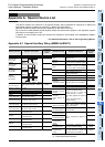
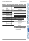
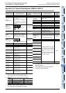
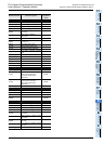
Appendix A-2 Special Data Register (D8000 to D8511)
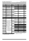
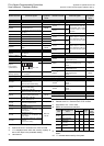
Appendix A-2 Special Data Register (D8000 to D8511)
*1. “4” is displayed even when the memory capacity is
set to 16 K steps in the parameter setting.
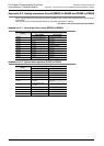
*2. D8003 becomes the undermentioned content.
*3. Indicated value includes waiting time of constant
scan operation (when M8039 is activated).
*4. The values of Z1 to Z7 and V1 to V7 are stored in
D8182 to D8195.
*5. FX
3S-30M/E-2AD is not supported.
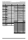
*6. Executed at END instruction.
Number and name Content of register
Correspond-
ing special
device
PLC status
D 8000
Watchdog timer
Default value is 200 ms
(in 1 ms steps)
(Writes from system ROM at power
ON)
Value overwritten by program is
valid after END or WDT instruction
execution.
-
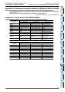
[D]8001
PLC type and
system version
D8101
[D]8002
Memory capacity
• 2...2 K steps
• 4...4 K steps
*1
D8102
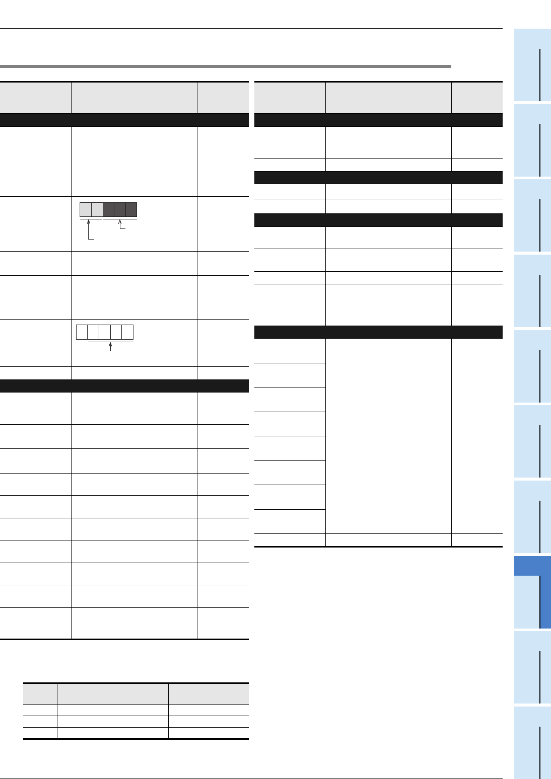
[D]8003
Memory type
Stores the memory type (built-in
EEPROM or memory cassette) and
the PROTECT switch ON/OFF
status of the memory cassette.
*2
-
[D]8004
Error number M
M8004
[D]8005 to [D]8009 Not used -
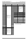
Clock
[D]8010
Present scan time
*3
Accumulated instruction-execution
time from 0 step
(in units of 0.1 ms)
-
[D]8011
Minimum scan time
*3
Minimum value of scan time
(in units of 0.1 ms)
-
[D]8012
Maximum scan time
*3
Maximum value of scan time
(in units of 0.1 ms)
-
D 8013
Second data
0 to 59 seconds
(for real time clock)
-
D 8014
Minute data
0 to 59 minutes
(for real time clock)
-
D 8015
Hour data
0 to 23 hours
(for real time clock)
-
D 8016
Day data
1 to 31 days
(for real time clock)
-
D 8017
Month data
1 to 12 months
(for real time clock)
-
D 8018
Year data
2 digits of year data (0 to 99)
(for real time clock)
-
D 8019
Day-of-the-week
data
0 (Sunday) to 6 (Saturday)
(for real time clock)
-
Present
value
Type of memory Protect switch
02H EEPROM memory cassette OFF
0AH EEPROM memory cassette ON
10H Built-in memory in PLC -
2 8 1 0 0
FX
3S
Series
Version 1.00
8 0 6 1
8061 to 8068 (When M8004 is ON)
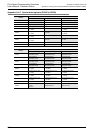
Number and name Content of register
Correspond-
ing special
device
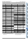
Input filter
D 8020
Input filter
adjustment
Input filter value of X000 to X017
(Default: 10 ms)
-
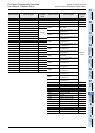
[D]8021 to [D]8027 Not used -
Index register Z0 and V0
[D]8028
Value of Z0 (Z) register
*4
-
[D]8029
Value of V0 (V) register
*4
-
Analog volume and constant scan
[D]8030
*5
Value of analog volume
VR1 (Integer from 0 to 255)
-
[D]8031
*5
Value of analog volume
VR2 (Integer from 0 to 255)
-
[D]8032 to [D]8038 Not used -
D 8039
Constant scan
duration
Default: 0 ms (in 1 ms steps)
(Writes from system ROM at power
ON)
Can be overwritten by program
M8039
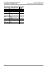
Stepladder
[D]8040
*6
ON state number 1
The smallest number out of active
state ranging from S0 to S255 is
stored in D8040 and the second-
smallest state number is stored in
D8041.
Active state numbers are then
sequentially stored in registers up to
D8047 (Max. 8 points).
M8047
[D]8041
*6
ON state number 2
[D]8042
*6
ON state number 3
[D]8043
*6
ON state number 4
[D]8044
*6
ON state number 5
[D]8045
*6
ON state number 6
[D]8046
*6
ON state number 7
[D]8047
*6
ON state number 8
[D]8048 to [D]8059 Not used -