


6 Examination of System Configuration
6.1 Configuration of a Whole System
49
FX3S Series Programmable Controllers
User's Manual - Hardware Edition
1
Introduction
2
Features and
Part Names
3
Product
Introduction
4
Specifications
5
Version and
Peripheral
Devices
6
System
Configuration
7
Installation
8
Preparation and
Power Supply
Wiring
9
Input Wiring
10
High-Speed
Counters
6. Examination of System Configuration
6.1 Configuration of a Whole System
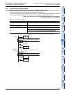
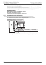
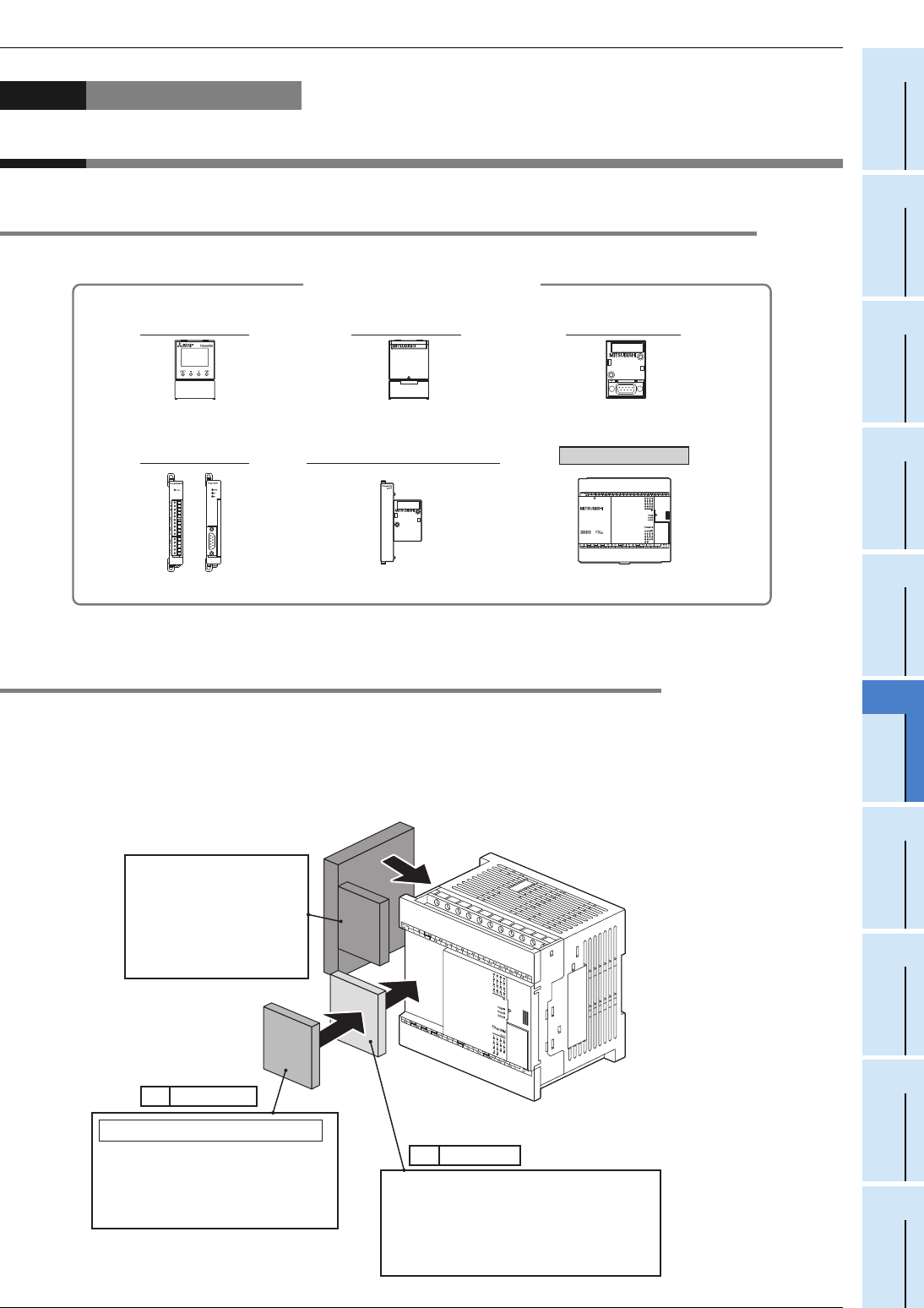
The configuration of a whole system is shown below as an example.
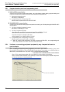
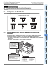
6.1.1 Expansion board/connector conversion adapter/memory cassette system
configuration
One expansion board or connector conversion adapter, and one memory cassette can be connected.
The figure below shows the combination of each product and the available connection positions.
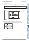
• 1st position: An expansion board, connector conversion adapter, display module or memory cassette can
be connected.
• 2nd position: A display module or memory cassette can be connected.
Main unit
Expansion boards
Configuration of a whole system
Special adapters
Display module
Connector conversion adapter
Memory cassette
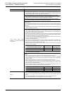
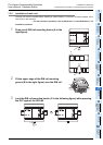
Connect a connector
conversion adapter to the
1st position of the BD slot.
The FX
3S
-5DM or
FX
3G
-EEPROM-32L
can be connected to the
2nd position.
BD 2nd position
BD 1st position
FX
3S
-5DM, FX
3G
-EEPROM-32L
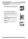
When the 1st position is used by
an expansion board or connector
conversion adapter,
the FX
3G
-EEPROM-32L can be
connected to the 2nd position.
• FX
3G
-4EX-BD
• FX
3G
-232-BD
• FX
3G
-485-BD
• FX
3G
-2AD-BD
• FX
3G
-8AV-BD
• FX
3G
-EEPROM-32L
• FX
3G
-2EYT-BD
• FX
3G
-422-BD
• FX
3G
-485-BD-RJ
• FX
3G
-1DA-BD
• FX
3S
-5DM