


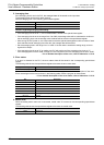
11 Use of Built-in Analog
103
FX3S Series Programmable Controllers
User's Manual - Hardware Edition
11
Built-in Analog
12
Output Wiring
13
Wiring for
Various Uses
14
Test Run,
Maintenance,
Troubleshooting
15
Other Extension
Units and
Options
16
Display Module
(FX
3S
-5DM)
17
Memory
Cassette
A
Special Devices
(M8000-, D8000-)
B
Instruction List
C
Discontinued
models
11.3 Built-in analog input function
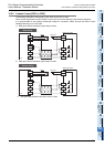
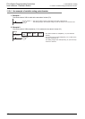
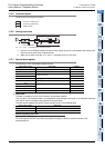
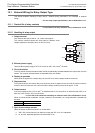
11.3.5 Terminal layout
Terminal layout is arranged as follows:
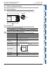
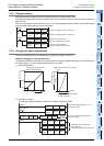
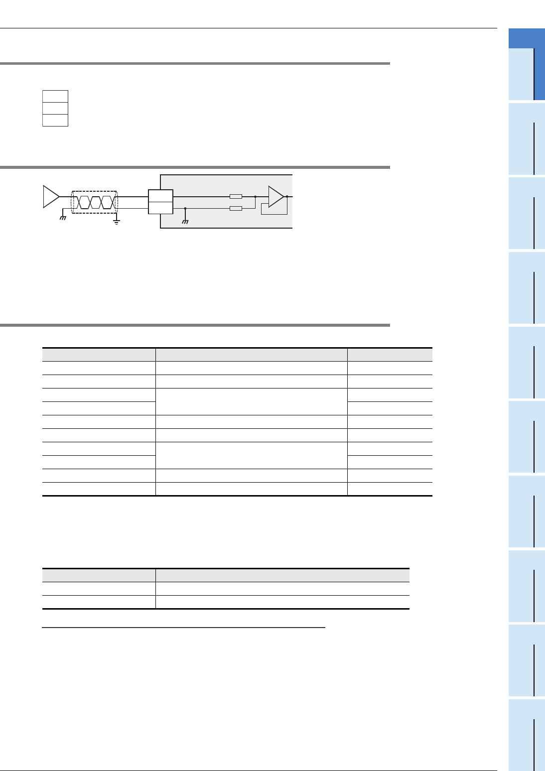
11.3.6 Analog input line
*1. Use the 2-core shielded twisted pair cable for the analog input lines, and separate the analog input
lines from other power lines or inductive lines.
*2. Make sure to short-circuit the "V+" and "V-" terminals when ch is not used.
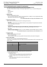
11.3.7 Special data register
The following is a list of associated special devices.
1. Input data
The data converted by the PLC will be stored in special data registers.
The converted A/D immediate data or averaged data (data average conforming to the specified averaging
time) will be stored in the above data registers as the input data.
The special data registers that store the input data are shown in the following table:
Caution regarding input data
Input data is for reading only.
Do not change (rewrite) the input data using sequence program, indicator, or device monitor of the
programming tool.
Special data register Description Attribute
D8270 Channel-1 input data R
D8271 Channel-2 input data R
D8272
Unused (Do not use.)
-
D8273 -
D8274 Averaging time for channel-1 (Setting range: 1 to 4095) R/W
D8275 Averaging time for channel-2 (Setting range: 1 to 4095) R/W
D8276
Unused (Do not use.)
-
D8277 -
D8278 Error status R
D8279 Model code R
Special data register Description
D8270 Channel-1 input data
D8271 Channel-2 input data
V1+
V2+
V-
• • •
channel 1 analog input
• • •
channel 2 analog input
• • •
COM terminal
V□ +, I□ +, ch□ : □ represents the channel number.
Class-D grounding
*1
*2
ch□
33 kΩ
82.7 kΩ
V□+
V-