4-5
Note that the output of the Wide Band Preamp (IR-IN)
is also directed to the SYS-5 µPC. This connection
was not used in the V19 and V21. It enables the Learn-
ing feature. The signals from the units Remote are memo-
rized by the SYS-5 circuitry.
Serial Data Lines
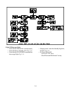
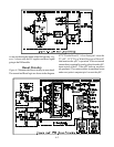
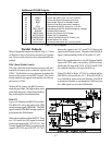
Figure 4-4 shows the Serial Data lines and indicates
what circuits they control. ICs IC7B00~IC7B03 are
level shift ICs, changing the 3.3V data and clock lines
from IC7A00 to 5V lines.
In previous sets the TV Control circuitry used two
E2PROM Memory ICs, one on the PCB-SIGNAL and
one on the PCB-TERMINAL. Due to the changes in
design only one E2PROM is required, and for factory
alignment purposes it is located on PCB-TERMINAL.
In the V23 the DTV Tuner and Modulator are separate
from the DM Module. The DTV Tuner is controlled by
the TDAT and TCLK lines from the DM Module. The
DM Module also controls the MLink (DVI) circuitry,
through the DVI-RXD and DVI-TXD lines.
Figure 4-4 also shows that the DM Module receives
and processes the signals from the Card Reader.
µPC Parallel Inputs
The parallel inputs to the µPC are status inputs or sig-
nals inputs required for control purposes.
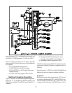
AC-OFF Input
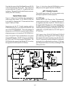
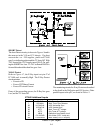
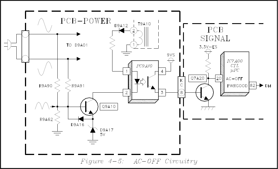
Informs the µPC if AC Power is lost. The monitoring
circuit is shown in Figure 4-5. Samples of the input AC
are applied to the base of Q9A10. D9A16 removes
the negative half of the sine waves. The remaining posi-
tive half cycles keep Q9A10 conducting. With Q9A10
conducting PC9A10 conducts, turning Q7A20 On. The
conduction of Q7A20 holds the AC-OFF input to
IC7A00 Low.
If AC power is lost, Q9A10, PC9A10 and Q7A20 all
quit conducting, allowing pin 20 of IC7A00 to go High.
This informs the Control circuitry power has been lost.
The µPC responds by rapidly storing all user program-
ming and service adjustments to memory. It also out-
puts a High on the Power Good line, informing the DM
of the power loss.


